
Related Manuals for Megger VLF Sinus


Summary of Contents for Megger VLF Sinus
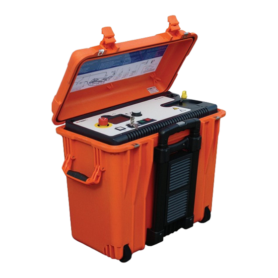
- Page 1 VLF Sinus 34 kV VLF Test System USER GUIDE Issue: A (05/2022) - EN Article number: 128312971...
- Page 3 Megger All rights reserved. No part of this handbook may be copied by photographic or other means unless Megger have before-hand declared their consent in writing. The content of this handbook is subject to change without notice. Megger cannot be made liable for technical or printing errors or shortcomings of this handbook.
- Page 4 This warranty does not apply to faults in the software supplied. During the period of warranty, Megger agree to repair faulty parts or replace them with new parts or parts as new (with the same usability and life as new parts) according to their choice.
-
Page 5: Table Of Contents
Contents Safety Advices ....................... 6 General Notes ..........................6 General Cautions and Warnings....................7 Technical Description ....................9 General Description ........................9 Technical Data ......................... 10 Testable Cable Capacities ......................11 Connectors and Controls ......................12 Setting Up the System ....................13 Electrical Connection ........................ -
Page 6: Safety Advices
This manual contains basic instructions on commissioning and operating the VLF Sinus 34 kV. For this reason, it is important to ensure that the manual is available at all times to authorised and trained personnel. Any personnel who will be using the devices should read the manual thoroughly. -
Page 7: General Cautions And Warnings
• If, contrary to the regulations, any other extinguishing agent is used for fire fighting, this may lead to damage at the electrical installation. Megger disclaims any liability for consequential damage. Furthermore, when using a powder extinguisher near high- voltage installations, there is a danger that the operator of the fire extinguisher will get an electrical shock from a voltage arc-over (due to the powder dust created). - Page 8 EN 50191 as well as country-specific regulations and standards must be observed. • The VLF Sinus 34 kV generates a dangerous voltage of up to ±24 kV during testing. This is supplied via a HV cable to the test object.
-
Page 9: Technical Description
A detailed description of this use can be found in the operating manual of the tan Delta test attachment. Features The VLF Sinus test system unites the following features and functions in a single device: • Full AC voltage testing up to 24 kV (sine wave voltage) •... -
Page 10: Technical Data
Technical Data The VLF Sinus 34 kV test system is defined by the following technical parameters: Parameter Value Output voltage (sine wave) Testing max. 24 kV (33.9 kV PEAK Loss factor measurement with max. 21,2 kV (30 kV PEAK the tan Delta test attachment Source output current 8.8 mA... -
Page 11: Testable Cable Capacities
Testable Cable Capacities Introduction The following diagrams show the relation of the test frequency to the connected load capacitance and the set test voltage. If the set test frequency cannot be used due to the restrictions visible here, the system prompts for a switch to the lowest possible frequency or, if automatic frequency adaption is enabled, immediately switches to this frequency. -
Page 12: Connectors And Controls
Connectors and Controls The system has the following connectors and controls: Element Description USB slot Emergency off button Ethernet interface for servicing and remote control On/off button HV “interlock” key switch “HV ON” button Display Rotary encoder Fuses F1 / F2 (2 x T4A) Power supply socket Protective earthing connection HV output... -
Page 13: Setting Up The System
Setting Up the System Safety instructions for setting up • Select a location which is sufficient for the weight and size of the system and ensures that it stands securely. WARNING • When setting up the testing system, ensure that it does not impair the function of any other systems or components. - Page 14 Connection diagram The following figure shows the simplified connection diagram: 110 V … 230 V Cable test in DC+, DC-, VLF Sinus or VLF Rectangle mode 50 / 60 Hz 110 V … 230 V Sheath testing and pinpointing 50 / 60 Hz...
-
Page 15: Switching On The System
Start button (see section 4.4). If instead you need to change the system or test settings in preparation for the upcoming test, the Menu button takes you to the settings menu (see section 4.3). VLF Sinus 34 kV 10.10.2008 / 14:06:19 Mode: VLF Sinus 5.0kV... -
Page 16: Stand-Alone Operation
Stand-Alone Operation Basics of Operation Operation with rotary Navigation within the menus is done using the rotary encoder as follows: encoder Turning selecting Pressing confirming (“Enter” function) The currently selected menu item can be identified by its background colour. selected selected With the aid of the rotary encoder, the individual menus can be accessed and values can be entered. -
Page 17: Safety Measures
Safety Measures Introduction Once high voltage is enabled, the system's safety circuit continuously checks all safety- relevant parameters and switching operations of the system. Should the safety circuit detect a deviation from the monitored requirements while in high voltage mode, the system automatically switches back to the 'Ready for operation' state. -
Page 18: Settings
If you instead wish to change the operation mode, the test parameters or the system settings, selecting Menu will take you to the settings menu: VLF Sinus 34 kV 10.10.2008 / 14:06:19 Mode:... -
Page 19: Device Settings
Only update with firmware provided by Megger. Do not switch off the system during the update. If you do, the system will have to be repaired by Megger Service. Service A password-protected service menu which can only be accessed by a service technician. -
Page 20: Changing The Test Settings
4.3.2 Changing the Test Settings Changing the To select the operation mode, select Mode from the settings menu (see page 18). operation mode Mode: VLF-Sinus VLF-Sinus Sheath Test VLF- Sheath Back Rectangle Pinpointing Menu item Description VLF-Sinus In this mode, the test object is tested with a true VLF sine wave voltage of up to 24 kV (33.9 kV ) and a frequency of between 0.01 Hz and... - Page 21 Range (see next page) during operation. Test For the modes “VLF Sinus” and “VLF Rectangle”, the test frequency frequency can be set in increments of 0.01 Hz between 0.01 Hz and 0.1 Hz. Alternatively, automatic frequency calculation (auto) can also be activated.
-
Page 22: Testing / Pinpointing
Correspondingly, a continuous test is always logged as failed test. RMS | PEAK This menu item can be used in “VLF Sinus” mode to specify whether the voltage values on the display are to be shown as effective (RMS) or PEAK values. - Page 23 Test sequence The following flow chart describes the test sequence in principle: Start menu Start failed After appr. 5 seconds Query of safety circuit without user input Prompt to press the “HV ON” button HV ON Automatic load recognition Automatic AC modes only frequency adaption enabled?
- Page 24 Status information While the test is running, the user is kept continually updated regarding current during the test parameters and results. The screen content does differ in dependence of the respective procedure operation mode as shown in the figures below: AC modes 00:42:29 3.8kV(RMS)
- Page 25 Detail view The Details button can be used to display details on the measurement in progress at any time: V(Peak) =-5.0kV V(RMS) =3.8kV I(PEAK) =-4.2mA I(RMS) =3.0mA RLoad =>100M CLoad =1.45μF =0.10Hz t_set =60:00 -5kV 4:10 4:15 Scroll Back On the right side of the detail view, the test voltage characteristics (AC voltage test) or the characteristics of the leakage current (DC voltage test) are drawn in real time in a diagram.
- Page 26 Completion / A running test can be completed / interrupted in various ways. Cancellation of a test The user can interrupt the test by means of the following: • Activation of the Stop button with the aid of the rotary encoder •...
-
Page 27: Remote Control
Remote Control Introduction The VLF Sinus test system can be remotely-controlled using a notebook with the respective software. This is particularly required if you want to operate the test system as voltage source for the Tan Delta Test Attachment to measure the loss factor tanδ. -
Page 28: Further Processing Of The Log Data
The log files can be easily opened and further processed with standard programs such as Word and Excel (or comparable applications). In addition, Megger offers a lightweight tool called Easyprot for visual processing of these log files. Please download the latest version of this tool from the download section of our website (www.Megger.com). -
Page 29: Repair And Maintenance
Repair and Maintenance Maintenance Repairs and service must only be done by Megger or authorised service departments of Megger. Megger recommends having the equipment serviced and checked once per year at a Megger service location. Megger also offers direct on-site support. Please contact our service office for more information. - Page 31 Tento symbol indikuje, že výrobek nesoucí takovéto označení nelze likvidovat společně s běžným domovním odpadem. Jelikož se jedná o produkt obchodovaný mezi podnikatelskými subjekty (B2B), nelze jej likvidovat ani ve veřejných sběrných dvorech. Pokud se potřebujete tohoto výrobku zbavit, obraťte se na organizaci specializující se na likvidaci starých elektrických spotřebičů...
Need help?
Do you have a question about the VLF Sinus and is the answer not in the manual?
Questions and answers