Advertisement
Available languages
Available languages
MOUNTING INSTRUCTIONS.
1. Choose the mounting position for the GS625 sensors on the struc-
ture to be protected, having regard to the structure's ability to
transmit vibrations, etc. Note that the universal sensor can be
mounted on a horizontal plane e.g. on a flat ceiling or under a
door lintel.
2. Remove the sensor cover and secure the base-plate to the struc-
ture either vertically or horizontally as required.
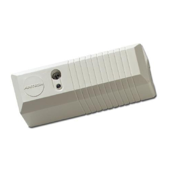
3. Orientate the sensor module so that the ARITECH logo is up-
right and in the readable position (fig. 1).
4. Route cabling into the unit and wire the unit as shown in fig. 3, 4 or 5.
5. Ensure that the screws of the sensor module (fig. 1) are secure.
6. Apply power to the system. The alarm relay and the LED of each
unit are activated for a period of 4 seconds.
7. Enable the LED indication by removing jumper J1 (fig. 2).
8. Program each unit for GROSS ATTACK and PULSE COUNT
(table 1).
9. Disable the LED indication by placing jumper J1.
10. Replace the cover and secure it with the screw.
Fig. 1. Sensor head
WIRING.
Standard application (fig. 3).
The GS625 incorporates two on-board 4k7 End of Line (EOL) resis-
tors in series with the alarm and tamper contacts (fig. 3. J2 and J3.)
J2 enables the tamper loop EOL-resistor and J3 the alarm loop EOL-
resistor.
In systems with separate alarm and tamper loops the devices must
be connected like shown in fig. 3. Remove the jumpers J2 and J3 of
the last device.
Common ground application. (fig. 4).
In systems where the alarm and tamper loop use a common ground
wire, the devices must be connected like shown in fig. 4. Remove
both jumpers J2 and J3 of the last device and place a jumper like
indicated to connect the end of both loops together. This eliminates
the need for and external connection between both loops.
Only one terminal (3 or 5) has to connected to the ground wire.
Dual loop application (fig. 5).
The GS625 can also be used in dual loop applications. Connect the
devices like indicated in fig. 5. Enable the tamper EOL-resistor by
removing jumper J2. Do NOT remove jumper J3. Connect terminal 3
and 5 of the last device together and connect an external 4k7 resis-
tor in parallel with all alarm contacts like indicated in fig. 5.
Fig. 2. Connection data
LED ENABLE/DISABLE.
For test purposes the LED of the device can be enabled by removing
the LED-ENABLE jumper J1.
The LATCH input must NOT be activated to enable the LED indica-
tion for testing! Activation of the LATCH input overrules the LED en-
able jumper setting and all LED indications are disabled.
GS625 STAND ALONE INERTIA SHOCK DETECTOR
Fig. 3. Standard application.
Fig. 4. Common ground application.
Fig. 5. Dual loop application
- 1 -
Advertisement
Table of Contents

Related Manuals for Aritech GS625


Summary of Contents for Aritech GS625
- Page 1 GS625 STAND ALONE INERTIA SHOCK DETECTOR MOUNTING INSTRUCTIONS. 1. Choose the mounting position for the GS625 sensors on the struc- ture to be protected, having regard to the structure’s ability to transmit vibrations, etc. Note that the universal sensor can be mounted on a horizontal plane e.g.
- Page 2 ALARM MEMORY. The GS625 can latch an alarm event into a memory. The memory function can be enabled by the LATCH input. When the system is armed, the LATCH-input of the detector should be acti- vated (apply +12 V to input).
- Page 3 MONTAGE INSTRUCTIES. 1. Kies op de te bewaken structuur een plaats om de GS625- detectoren te monteren. Houd hierbij rekening met het vermogen van de structuur om trillingen, enz. door te geven. Let er ook op dat de universele sensor op een horizontaal vlak gemonteerd wordt, zoals aan een vlak plafond of onder de draagbalk boven een deur.
- Page 4 Als gedurende een lange tijd het signaal van de inertiesensor hoog blijft, dan 5. Gebruik de brute-aanvalsschakelaars 3 & 4 voor het instellen van de geeft dit aan dat de sensor niet correct geïnstalleerd is (d.w.z. het ARITECH- gevoeligheid en voer hevige schokken op de structuur uit, waarbij de LED...
Need help?
Do you have a question about the GS625 and is the answer not in the manual?
Questions and answers