Advertisement
Quick Links
Little Giant
P. O. Box 12010
Oklahoma City, OK 73157-2010
405.947.2511 • Fax: 405.947.8720
www.LittleGiant.com
customerservice@lgpc.com
INTRODUCTION
This instruction sheet will provide you with information required to safely own and operate
the Little Giant 10E and 10S series pumps. The pump you have purchased is a submers-
ible effluent pump for use in basins or lift stations and suitable for pumping sewage,
effluent, wastewater and other non-explosive, non-corrosive liquids. The 10S Series sew-
age ejector pumps have a 2" spherical solids handling capability. The 10E Series sewage
effluent pumps have a 3/4" spherical solids handling capability.
This instruction sheet covers the standard models in this pump series. This form is applicable
to other models in this series not listed by catalog number in the replacement parts list
section of this pamphlet. If the catalog number of your pump is not listed in the replacement
parts section, then caution should be exercised when ordering replacement parts. Always
give the catalog number of your pump when ordering replacement parts.
The Little Giant unit you have purchased is of the highest quality workmanship and
material. It has been engineered to give you long and trouble-free service.
Little Giant pumps are carefully inspected, tested, and packaged to insure safe operation
and delivery. When you receive your pump, examine it carefully to determine that there
are no broken or damaged parts that may have occurred during shipment. If damage has
occurred, make notation and notify the firm from which you purchased the pump. They
will assist you in replacement or repair, if required.
Read instructions carefully before attempting to install, operate or service the Little Giant
pump. Know the pump applications, limitations, and potential hazards. Protect yourself
and others by observing all safety information. Failure to comply with instructions could
result in personal injury and/or property damage. Retain instructions for future refer-
ence.
SAFETY GUIDELINES
1. Do not use to pump flammable or explosive fluids such as gasoline, fuel oil, kerosene,
etc. Do not use in explosive atmospheres. Pump should only be used with liquids
compatible with pump component materials.
2. Do not handle pump with wet hands or when standing on a wet or damp surface, or
in water.
3. Do not use power cord for lifting the pump.
4. This pump is supplied with a grounding conductor and/or grounding-type attach-
ment plug. To reduce the risk of electric shock, be certain that it is connected to a
properly grounded grounding-type receptacle.
5. The National Electric Code requires a ground fault circuit interrupter (GFCI) be installed
in the branch circuit supplying fountain equipment, pools, etc.
6. In any installation where property damage and/or personal injury might result from an
inoperative or leaking pump due to power outages, discharge line blockage, or any
other reason, a backup system(s) and/or alarm should be used.
7. Support pump and piping when assembling and when installed, failure to do so may
cause piping to break, pump to fail, motor bearing failures, etc.
8. This pump's motor housing is filled with a dielectric oil for motor heat transfer and
lifetime lubrication of the bearings. This oil is non-toxic to aquatic life; however,
suffocation can occur if oil is left on the water surface. If oil escapes the motor housing,
it can be removed from the surface quickly by placing newspapers on the water surface
to soak up the oil.
9. The pump motor is equipped with an automatic resetting thermal protector and may
restart unexpectedly. Protector tripping is an indication of motor overloading as a result
of excessively high or low voltage, inadequate wiring, incorrect motor connections or
a defective motor or pump.
ELECTRICAL CONNECTIONS
1. Check the pump label for proper voltage required. Do not connect to voltage other
than that shown.
2. If pump is supplied with a 3-prong electrical plug, the third prong is to ground the
pump to prevent possible electrical shock hazard. DO NOT REMOVE the third prong
from the plug. A separate branch circuit is recommended. Do not use an extension
cord. Do not cut plug from the cord. If the plug is cut or the cord is shortened, then
this action will void the warranty.
3. If the cord is equipped with stripped lead wires, such as on 230V models, be sure
that the lead wires are connected to a power source correctly. The green/yellow wire
is the ground, the other two are live.
4. Check local electrical and building codes before installation. The installation must
be in accordance with their regulations as well as the most recent National Electrical
Code (NEC).
5. To conform to the National Electrical Code all pumps must be wired with 14 AWG or
larger wire. For runs to 250', 14 AWG wire is sufficient. For longer runs, consult a
qualified electrician or the factory.
6. Pump should be connected or wired to its own circuit with no other outlets or equipment
in the circuit line. Fuses and circuit breaker should be of ample capacity in the
electrical circuit.
7. The flexible PVC jacketed cord assembly mounted to the pump must not be modified
in any way, with the exception of shortening the cord to fit into a control panel. Any
splice between the pump and the control panel must be made within a junction box
and mounted outside of the basin and comply with the National Electrical Code.
1. Pump must be installed in a suitable gas tight basin which is at least 18" in diameter
and 24" deep, and vented in accordance with local plumbing codes.
2. 10E series features 1-1/2" female NPT discharge. 10S series features 2" female NPT
discharge.
3. Pump must be placed on a hard level surface. Never place pump directly on clay,
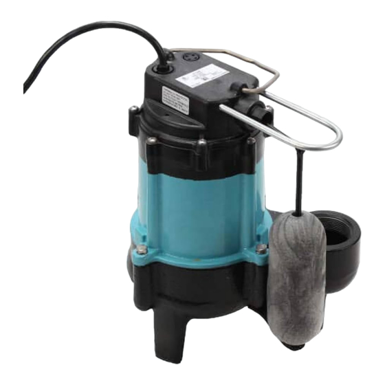
10E-CIA-SFS
10S-CIA-SFS
Submersible
Effluent Pumps
OPERATION
Figure 1.
earth or gravel surfaces.
4. A check valve must be used in the discharge line to prevent backflow of liquid into
the basin. The check valve should be a free flow valve that will easily pass solids. Drill
a 3/16" hole in the discharge pipe approximately 1"–2" above the pump discharge
connection and below check valve to prevent air locking the pump.
CAUTION: For best performance of check valves, when handling solids install in a
horizontal position or at an angle of no more than 45°. Do not install check valve in a
vertical position, as solids may settle in valve and prevent opening on start-up.
5. Do not attempt to restrict the intake side of these pumps. Restricting the intake may
cause damage to the seal and may starve the pump. If you require reduced flow
rates, then place a valve on the discharge side of the pump or if flexible vinyl tubing
is used, a clamp can be used on the tubing to restrict the flow.
6. Do not let the unit operate dry. It is designed to be cooled by pumping fluid. You may
damage the seal and the motor may fail if the pump is allowed to run dry.
7. If the unit is going to be idle for a period of time, follow the cleaning instructions
outlined in the next section. Do not let the unit freeze in the wintertime. This may
cause cracking or distortion that may destroy the unit.
TESTING PUMP OPERATION
1. These pumps are equipped with a float operated mechanical switch.
2. When these pumps are installed in a basin with a sealed cover, switch operation cannot
be observed. The sump cover usually will have a spare hole that is plugged with a
rubber plug. This plug can be removed and switch operation can be observed.
3. Plug power cord into a grounded receptacle with voltage consistent with pump voltage
as indicated on pump nameplate.
4. Run water into pump until pump starts.
5. Be sure gate valve in discharge line is open.
6. Allow pump to operate through several on-off cycles.
SERVICE INSTRUCTIONS
MAKE CERTAIN THAT THE UNIT IS DISCONNECTED FROM THE POWER SOURCE
BEFORE ATTEMPTING TO SERVICE OR REMOVE ANY COMPONENT!
1. If pump does not operate properly, consult the troubleshooting chart. If trouble cannot
be located with the steps shown, consult your pump dealer or take pump to a Little
Giant authorized service center.
2. Do not remove the three socket head cap screws (item #11). The motor section on
your pump is permanently lubricated with dielectric oil and sealed at the factory.
Removal of these socket head cap screws by anyone other than an authorized Little
Giant service center will break the seal and void the warranty.
3. Periodic cleaning of the pump parts will prolong the LIFE and EFFICIENCY of the
pump. Refer to Figure 2 for the assembly and disassembly of the pumping head.
4. On 10E Series: Remove five screws (item #23) that hold screen base and base plate
to volute/plate.
On 10S Series: Remove four hex bolts (item #39) that hold volute to plate. Remove
volute.
Do not use strong solvents on impeller.
5. Be sure impeller turns freely after cleaning.
6. WARNING: DO NOT REMOVE IMPELLER. REMOVAL OF IMPELLER REQUIRES
SPECIAL TOOLS AND IS TO BE DONE ONLY BY AN AUTHORIZED SERVICE
CENTER. DO NOT REMOVE MOTOR HOUSING COVER. WARRANTY IS VOID IF
MOTOR HOUSING COVER, IMPELLER OR SEALS HAVE BEEN REMOVED. ANY
REPAIR ON MOTOR MUST BE DONE BY AN AUTHORIZED LITTLE GIANT SERVICE
CENTER.
7. Be certain power cord is in good condition and contains no nicks or cuts.
Advertisement

Related Manuals for Little Giant 10E-CIA-SFS


Summary of Contents for Little Giant 10E-CIA-SFS
- Page 1 This instruction sheet will provide you with information required to safely own and operate the Little Giant 10E and 10S series pumps. The pump you have purchased is a submers- ible effluent pump for use in basins or lift stations and suitable for pumping sewage, effluent, wastewater and other non-explosive, non-corrosive liquids.
- Page 2 Little Giant at Oklahoma City, Oklahoma, or such other place as Little non-abrasive liquids not above 140°F with up to 3/4" spherical solids (1/2" on 6E models) Giant may designate, freight prepaid.
Need help?
Do you have a question about the 10E-CIA-SFS and is the answer not in the manual?
Questions and answers