Table of Contents
Advertisement
Quick Links
Advertisement
Table of Contents

Summary of Contents for WABASH COMMUNICATIONS MBS-1P
- Page 1 MBS-1P Installation Guide ® APRIL 2003 Heavy Duty Trailer ABS by Wabash National...
- Page 2 Notes, Cautions, and Warnings This manual contains Notes, Cautions, and Warnings in addition to the assembly instructions. Notes: Provide additional comments to help with installation and set up. Cautions: Provide notification of situations that can cause damage to machinery and tools. Warnings: Provide alerts to situations that can cause personal injury or death.
- Page 3 MBS-1P Installation ® MBS Identification Before service or diagnostics is performed on a Wabash MBS unit, the system design must be verified. Do not rely on labels or verbal descriptions to identify the MBS system. Refer to the illustration below and compare the marking in the lower right-hand corner of the ECM with the location(s) of the wheel speed sensor wire or cable on the trailer’s axle(s).
-
Page 4: Table Of Contents
Wabash MBS-1P ABS Introduction ....... 1 MBS-1P System Components ........2 General Air Brake Requirements . -
Page 5: Wabash Mbs-1P Abs Introduction
® Wabash MBS-1P ABS Introduction The Wabash MBS-1P ABS enhances the original MBS-1 system by adding Power Line Carrier (PLC) and expanding the number of configuration options. The system can be configured with either two or four sensors and either one or two pneumatic control modules. -
Page 6: Mbs-1P System Components
MBS-1P Installation ® MBS-1P System Components Wabash’s MBS-1P system includes unique ABS components as well as interfacing with standard trailer components (see Figure 1). Refer to Figures 2 and 3 for part number and description of Wabash parts. Power Cable... - Page 7 Bosch ABS Sensor 10800126 Wabco ABS Sensor 10800068 Midland ABS Sensor 10800226 Bosch ABS Sensor Clip 10800009 Wabco ABS Sensor Clip 10800069 MidlandABS Sensor Clip 14401359 ABS Wiring Harness 14401744 ABS Malfunction Lamp Harness w/Diagnostic Switch 322UX031 Figure 2, MBS-1P System Components...
- Page 8 MBS-1P FLASH FOURTEEN TIMES TRAILER ANTI-LOCK BRAKE SYSTEM X 14 LOW VOLTAGE TO ABS A PRODUCT OF WABASH NATIONAL PLC-4 TRUCKS COMPATIBLE FLASH FIFTEEN TIMES X 15 DECAL PART NUMBER: WN#25000972 ELECTRONIC CONTROL MODULE 322UX024 Figure 3, MBS-1P System Components...
-
Page 9: General Air Brake Requirements
MBS-1P Installation ® General Air Brake Requirements FMVSS-121 identifies minimum requirements for air brake systems on commercial vehicles built in the U.S. (Requirements in Canada are covered under CMVSS-121 and are virtually identical.) These regulations cover requirements for new construction. Once put into operation, proper use and maintenance is covered under standards such as: •... -
Page 10: Abs
MBS-1P Installation ® Key Dates March 1, 1997 Tractors must be equipped to provide full time power to trailers. March 1, 1998 Newly manufactured trailers must be equipped with ABS. Some special use cases are exempt. (Refer to FMVSS-121 for specific details.) April 1, 2000 ABS required on newly manufactured Canadian Vehicles. -
Page 11: Power Requirements For Abs
MBS-1P Installation ® Power Requirements for ABS For trailers built after March 1 of 1998, the trailer wiring system must provide two sources of power for the antilock system. 1. Full-time power (when ignition is on) must be provided by the tractor. This full-time power source may be shared with other trailer circuits. -
Page 12: Color And Labeling
• Lights during vehicle operation to indicate a fault has occurred. In order for PLC to function, tractors and trailers must both be equipped with PLC versions of ABS. All Wabash National MBS-1P systems manufactured after March 1, 2001 are PLC capable. -
Page 13: Applications
MBS-1P Installation ® Applications The performance of the Wabash MBS-1P ABS depends upon proper installation of all components. Trailer suspension, axle configuration, and other brake components will affect the level of ABS performance. The “Sensed” and the “Controlled” axles must be considered prior to installation of the MBS-1P. - Page 14 #10800358 One valve One valve each side each side CONTROLLED AXLE CONTROLLED AXLE SENSED AXLE SENSED AXLE MBS-1P #10800358 MBS-1P #10800358 One valve One valve each side each side CONTROLLED AXLES CONTROLLED AXLES 322UX036 Figure 5, Wabash MBS-1P Application Chart...
- Page 15 Contact customer service for assistance when installing Contact customer service for assistance when installing ABS on units with axle spreads that exceed 11 feet. ABS on units with axle spreads that exceed 11 feet. 322UX035 Figure 6, Wabash MBS-1P Application Chart...
-
Page 16: Electrical System
MBS-1P Installation ® Electrical System The Antilock Control Module (ACM) consists of an Electronic Control Module (ECM) and a Pneumatic Control Module (PCM) combined as one unit. However, they are individually field replaceable. The wheel sensor, malfunction lamp, and power harnesses are connected to the ECM. -
Page 17: Pneumatic System
MBS-1P Installation ® Pneumatic System The PCM contains the pneumatic solenoids that physically control pressure in the service line to the relay valve. The 3/8" service line enters and exits the PCM through integrated quick connect fittings. The PCM also incorporates a quick exhaust valve that minimizes delays during brake release and helps purge contaminants that may enter the service control line. -
Page 18: Installation Of Electrical System
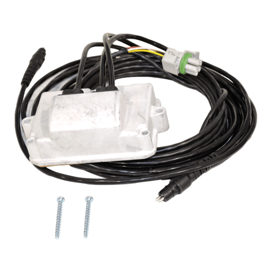
The sensor cables terminate in molded two-pin (industry standard) connectors. MBS-1P Cable Options The MBS-1P can be configured with either a long or short power cable. Refer to the system component charts on page 3 and 4 for specific system and part number information. - Page 19 MBS-1P Installation ® Power Sensor Harness Harnesses 322UX025 Figure 9, MBS-1P Components and Connectors...
-
Page 20: Circuit Requirements
A diagnostic switch is located near the ABS malfunction lamp. A malfunction lamp harness incorporating this switch is included in the MBS-1P kit. NOTE: While this feature is desirable, it is not essential. Diagnostic flash codes can also be activated from the tractor cab via the ignition switch. -
Page 21: Pneumatic System
Pneumatic System MBS-1P Location and Mounting The MBS-1P can be located some distance from the relay valve. The air line connecting the PCM to the relay valve should be 3 to 5 feet in length. This allows some mounting flexibility, provides good ABS performance, and complies with brake application and release timing requirements. -
Page 22: Plumbing Instructions
MBS-1P then 1/4" airline must be used from the R-12 to the TEV. Wabash requires the following pneumatic plumbing: 1. From “DEL” of MBS-1P, route 3/8" tubing to a tee at the relay valve. 2. From the tee at the top of the relay valve, route 1/4" tubing to the spring brake valve anti-compounding port. - Page 23 Note: Actual Component Locations May Vary 322UX014 Preferred Plumbing 2M Axle Control Spring Suspension w/Slider Supply Service MBS-1P Relay Valves Bulkhead Feedthru Spring Service Brake Gladhand Brake Note: Actual Component Locations May Vary 322UX016 Figure 12, MBS-1P “Downstream” Air Supply Configurations (Preferred Plumbing)
-
Page 24: Relay Valve
3/8" tube from the “DEL” port of the MBS-1P. The feed for the trailer spring brake valve can be taken from a tee connection upstream of the MBS-1P. Use a 3/8"... - Page 25 Note: Actual Component Locations May Vary 322UX015 Alternate Plumbing 2M Axle Control Spring Suspension w/Slider Supply Service MBS-1P Relay Valves Bulkhead Feedthru Spring Service Brake Gladhand Brake Note: Actual Component Locations May Vary 322UX017 Figure 13, MBS-1P “Upstream” Air Supply Configurations (Alternate Plumbing)
-
Page 26: Hub Installation
MBS-1P Installation ® Hub Installation On retrofit applications, ABS wheel hubs must be installed (see Figure 14). Purpose: to ensure hub installation is performed uniformly and consistently. Recommended tools: 1-15/16", 4-13/16", 4-3/8", 3-1/4", and 3-3/16" sockets, vice grips, band cutters, allen wrench pack, 5 lb. rubber mallet, 1/2"... - Page 27 MBS-1P Installation ® ABS Wheel Hub Non-ABS Wheel Hub (with Tone Ring) (without Tone Ring) 322UX039 Figure 14, ABS Wheel Hub Identification...
-
Page 28: Initial System Checkout
MBS-1P Installation ® Initial System Checkout Following initial installation or service of the MBS-1P system, perform the following checkout procedure to verify proper operation of the braking system. 1. Check each sensor for proper output. • Use a digital multimeter to read the sensor voltage. It should be in excess of 200 MV AC and should increase if the wheel is spun faster. -
Page 29: Abs System Diagnostics
When the system is first powered up, the ABS malfunction lamp will come ON for two seconds then go OFF, indicating the system has passed all self-tests. All MBS-1P units must pass operation checks before the trailer is placed in service. -
Page 30: Troubleshooting The System
FLASH FOURTEEN TIMES TRAILER ANTI-LOCK BRAKE SYSTEM X 14 LOW VOLTAGE TO ABS A PRODUCT OF WABASH NATIONAL PLC-4 TRUCKS COMPATIBLE FLASH FIFTEEN TIMES X 15 ELECTRONIC CONTROL MODULE DECAL PART NUMBER: WN#25000972 322UX034 Figure 16, MBS-1P Flash Code Identification Decal... -
Page 31: Entering The Flash Code Diagnostic Mode
MBS-1P Installation ® Entering the flash code diagnostic mode Fault identification is provided via flashes of the ABS malfunction lamp. To enter the flash code diagnostic mode, it must be possible to power the auxiliary circuit. On March 1997 and newer tractors, this circuit is switched with the ignition. -
Page 32: Current Faults
MBS-1P Installation ® Current Faults To access the flash code identification for a current fault, turn all power OFF to the ABS and perform the following steps. 1. Power the stop lamp circuit (red) and allow power to remain ON this circuit until the flash code has been identified (see step 3 below). - Page 33 MBS-1P Installation ® To identify the fault, the code will correspond to a specific fault found in the Flash Code Identification Table on page 35. Before any maintenance is performed, disconnect all power from the system. In the unlikely event that more than one fault is present, the malfunction lamp will not turn OFF at power up after the original fault is repaired.
-
Page 34: Stored Faults
MBS-1P Installation ® Stored Faults To access the flash code identification for a stored fault, turn all power OFF to the ABS and perform the following steps. NOTE: This procedure should only be required during annual routine maintenance or when there is an intermittent problem that does not show up at stationary power up. - Page 35 MBS-1P Installation ® Accessing Stored Fault Codes Turn all power OFF Power the stop lamp circuit (red). NOTE: Power with a light The malfunction lamp will light tester or by pulling down and then turn OFF on the trailer brake lever.
-
Page 36: Clearing Stored Faults
MBS-1P Installation ® Clearing Stored Faults To clear a stored fault, turn all power OFF to the ABS and perform the following steps: 1. Power the stop lamp circuit (red) and allow power to remain ON this circuit until the faults have been cleared (see step 3 below). The malfunction lamp will light with the stop lamps and turn OFF. - Page 37 MBS-1P Installation ® Clearing Stored Fault Codes Turn all power OFF Power the stop lamp circuit (red). NOTE: Power with a light Malfunction lamp will light tester or by pulling down and then turn OFF on the trailer brake lever.
-
Page 38: Malfunction Lamp Diagnostic Switch
® Malfunction Lamp Diagnostic Switch All MBS-1P units have a malfunction lamp diagnostic switch. This diagnostic switch is located in the malfunction lamp wiring harness, behind the base rail where the malfunction lamp is mounted. The diagnostic switch works much like turning the auxiliary circuit ON and OFF on a newer model tractor. - Page 39 NOTE: A two-sensor system does not contain 7 through 10 blink codes and a one-PCM system does not include the 11 blink code. The primary PCM is the PCM closest to the Electronic Control Module (ECM) and the secondary PCM is the furthest from the ECM. 322UX044 Figure 21, MBS-1P Flash Code Identification Table...
-
Page 40: Sensor Signal Faults (Trace)
® Sensor Signal Faults (Trace) While the trailer is moving, the MBS-1P continually compares the wheel speed signals from each sensor. If a wheel speed signal becomes inadequate, a sensor signal fault is detected. The malfunction lamp illuminates and the fault code is stored in memory. - Page 41 MBS-1P Installation ® Unlike a regular fault, on the next stationary power up after the fault is repaired, the lamp will remain ON because the fault trace is still present. Once the trailer moves, and assuming both signals are now present, the malfunction lamp will go out and ABS function will be available.
-
Page 42: Malfunction Lamp Failure
If the malfunction lamp does not illuminate on power up and the solenoids do not perform the self-test, check the following: • The MBS-1P may not be receiving power. Check the Weather Pack 5-way power connector for a loose connection. -
Page 43: Mbs-1P Electrical Schematic
Rear Axle Sensors Harness Side Trailer Mounted ABS Malfunction Lamp Front Speed Sensor (Road Side) Front Speed Sensor (Curb Side) Rear Speed Sensor (Road Side) Rear Speed Sensor (Curb Side) ECM Side Wheel Side 322UX004 Figure 23, MBS-1P Electrical Schematic... -
Page 44: Glossary
ABS. MBS-1P Wabash’s ACM that upgraded the basic MBS-1 to add PLC and more ABS configuration options. Like the MBS-1, the MBS-1P uses the industry standard VR wheel speed sensor. Pneumatic Control Module. Stored Faults... - Page 45 MBS-1P Installation ® Trace Fault A temporary record of a previous fault that slightly modifies malfunction lamp operation but does not affect ABS function. Wheel Speed Sensors Located either in the front and/or rear axle, depending on the geometry of each particular tandem, the wheel sensors receive wheel speed information.
- Page 46 MBS-1P Installation ® Notes ______________________________________________________________ ______________________________________________________________ ______________________________________________________________ ______________________________________________________________ ______________________________________________________________ ______________________________________________________________ ______________________________________________________________ ______________________________________________________________ ______________________________________________________________ ______________________________________________________________ ______________________________________________________________ ______________________________________________________________ ______________________________________________________________ ______________________________________________________________ ______________________________________________________________ ______________________________________________________________ ______________________________________________________________ ______________________________________________________________ ______________________________________________________________ ______________________________________________________________...
- Page 47 ® © 2003 Wabash Technology Corp. PGI57322-0403...
Need help?
Do you have a question about the MBS-1P and is the answer not in the manual?
Questions and answers