
Related Manuals for Quectel BC95-GR-TE-B


Summary of Contents for Quectel BC95-GR-TE-B
- Page 1 BC95-GR-TE-B User Guide NB-IoT Module Series Version: 1.0 Date: 2020-11-17 Status: Released www.quectel.com...
- Page 2 To the maximum extent permitted by law, Quectel excludes all liability for any loss or damage suffered in connection with the use of the functions and features under development, regardless of whether such loss or damage may have been foreseeable.
- Page 3 BC95-GR-TE-B User Guide Copyright The information contained here is proprietary technical information of Quectel wireless solutions co., ltd. Transmitting, reproducing, disseminating and editing this document as well as using the content without permission are forbidden. Offenders will be held liable for payment of damages. All rights are reserved in the event of a patent grant or registration of a utility model or design.
-
Page 4: About The Document
NB-IoT Module Series BC95-GR-TE-B User Guide About the Document Revision History Version Date Author Description Glenn GE/ 2020-11-10 Creation of the document Jerry WANG Glenn GE/ 2020-11-17 First official release Jerry WANG BC95-GR-TE-B_User_Guide 3 / 28... -
Page 5: Table Of Contents
Operating and Storage Temperatures ..................21 Mechanical Dimensions ........................23 5.1. Mechanical Dimensions of BC95-GR-TE-B ................23 5.2. Top and Bottom Views of BC95-GR-TE-B................24 BC95-GR-TE-B Kit and Accessories ....................25 6.1. BC95-GR-TE-B Kit........................25 6.2. BC95-GR-TE-B Kit Accessories ....................26 Appendix References ........................ - Page 6 Table 1: Key Features of BC95-GR-TE-B ....................9 Table 2: Interfaces of BC95-GR-TE-B ......................12 Table 3: Pin Connection Between BC95-GR-TE-B and STM32-L476RG MCU ........19 Table 4: Absolute Maximum Ratings ......................21 Table 5: Operating and Storage Temperatures ..................21 Table 6: Accessories List ..........................
- Page 7 Figure 8: STM32 Nucleo-64 Modification Diagram (Bottom View) ............18 Figure 9: ST-LINK Interface Displayed on PC ................... 19 Figure 10: Pin Connection Between BC95-GR-TE-B and STM32-L476RG MCU ........20 Figure 11: Dimensions of BC95-GR-TE-B (Top View) ................23 Figure 12: Top View of BC95-GR-TE-B ..................... 24 Figure 13: Bottom View of BC95-GR-TE-B ....................
-
Page 8: Introduction
Introduction To help you develop applications with Quectel BC95-GR module conveniently, Quectel supplies a corresponding development board (BC95-GR-TE-B) to test the module. This document helps you quickly understand BC95-GR-TE-B interface specifications, electrical and mechanical details and know how to use it. -
Page 9: Safety Information
Manufacturers of the cellular terminal should notify users and operating personnel of the following safety information by incorporating these guidelines into all manuals of the product. Otherwise, Quectel assumes no liability for customers’ failure to comply with these precautions. -
Page 10: Product Concept
BC95-GR-TE-B is an NB-IoT development board which supports Arduino interfaces. Designed in 70.0 mm × 74.0 mm × 1.6 mm form factor, BC95-GR-TE-B can be used to develop and debug applications which communicate with mobile network operators’ infrastructure equipment through NB-IoT radio protocols (3GPP Rel-13 and Rel-14). - Page 11 NB-IoT Module Series BC95-GR-TE-B User Guide ⚫ Upgrades software with QFlash ⚫ The default baud rate is 921600 bps Arduino Interfaces Connect with STM32 Nucleo-64 development board RESET Button Resets the BC95-GR module Physical Characteristics Size: (70.0 ± 0.15) mm × (74.0 ± 0.15) mm × (1.6 ± 0.15) mm...
-
Page 12: Functional Diagram
NB-IoT Module Series BC95-GR-TE-B User Guide 2.2. Functional Diagram The following figure shows the functional diagram of BC95-GR-TE-B. Power DC-DC J206 U201 BC95-GR J304 U101 LDO U202 J306 VDD_EXT J308 Switch Voltage- Micro USB USIM J302 level USB-UART J301 J303... -
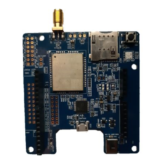
Page 13: Interface Distribution Diagram
NB-IoT Module Series BC95-GR-TE-B User Guide 2.3. Interface Distribution Diagram The following figure shows the interface distribution diagram of BC95-GR-TE-B. J305 J308 J102 J106 D304 J304 J111 J301 J103 J303 J206 J307 J306 D203 J302 S102 Figure 2: Interface Distribution Diagram of BC95-GR-TE-B The table below lists the interfaces of BC95-GR-TE-B with descriptions. - Page 14 NB-IoT Module Series BC95-GR-TE-B User Guide J206 External power supply interface USB-UART Interface J301 Supports two UART ports USIM Interface J303 Micro USIM card connector J305, J306, Arduino Interfaces Standard Arduino interfaces J307, J308 RF Antenna Interface J304 RF SMA connector Switches the communication objects of BC95-GR’s...
-
Page 15: Arduino Interface Definition
NB-IoT Module Series BC95-GR-TE-B User Guide 2.4. Arduino Interface Definition The following figure shows the Arduino interface definition of BC95-GR-TE-B. Figure 3: Arduino Interface Definition BC95-GR-TE-B_User_Guide 14 / 28... -
Page 16: Operation Procedures
Operating Procedures This Chapter mainly illustrates the two operating procedures of BC95-GR-TE-B: ⚫ You can use BC95-GR-TE-B alone to upgrade firmware and debug BC95-GR-based NB-IoT applications; ⚫ You can also use it together with an STM32 Nucleo-64 development board via the Arduino interface to develop STM32-based NB-IoT applications. -
Page 17: Operation Procedures
Switch J302 (UART Switch) to “MAIN UART TO USB” state. Connect J301 to a PC via a Micro USB cable. When BC95-GR-TE-B is connected to the computer, UART information is shown on the “Device Manager” of the PC. “USB Serial Port (COM154)”... -
Page 18: Operation Procedures With Multi-Boards
NB-IoT Module Series BC95-GR-TE-B User Guide 3.2. Multi-boards This section elaborates the operating procedure of using the BC95-GR-TE-B in conjunction with an STM32 Nucleo-64 development board. 3.2.1. Interface Diagram J305 J308 J304 J301 J303 J306 J307 J302 S102 Figure 6: Interface Diagram of Using Multi-boards... - Page 19 NB-IoT Module Series BC95-GR-TE-B User Guide Figure 7: STM32 Nucleo-64 Interface Diagram (Top View) SB13 SB14 SB62 SB63 Figure 8: STM32 Nucleo-64 Modification Diagram (Bottom View) BC95-GR-TE-B_User_Guide 18 / 28...
-
Page 20: Operation Procedures
Connect the Arduino interfaces to the STM32 Nucleo-64 development board by connecting J305, J306, J307 and J308 of BC95-GR-TE-B to CN5, CN6, CN8 and CN9 respectively. Connect CN1 of the STM32 Nucleo-64 development board to a PC via a Mini USB cable. When the BC95-GR module is powered on, device information is shown on the “Device Manager”... - Page 21 CN8-1 Ring indication signal +5 V +5 V CN6-5 +5 V 5.0 V power supply CN5-7, CN6-6, CN6-7 GND Ground The following figure shows the pin connection between BC95-GR-TE-B and STM32-L476RG MCU. RESET_N ADC0 POWER_EN UART_MCU_TX UART_MCU_RX Arduino Morpho BC95-GR-TE-B...
-
Page 22: Electrical Performance & Reliability
NB-IoT Module Series BC95-GR-TE-B User Guide Electrical Performance & Reliability 4.1. Absolute Maximum Ratings Absolute maximum ratings for power supply and voltage on digital and analog pins of the BC95-GR module are listed in the following table. Table 4: Absolute Maximum Ratings Parameter Min. - Page 23 NB-IoT Module Series BC95-GR-TE-B User Guide functions such as SMS and data transmission, without any unrecoverable malfunction. Radio spectrum and radio network will not be influenced, while one or more specifications, such as P may undergo a reduction in value, exceeding the specified tolerances of 3GPP. When the temperature returns to the operating temperature range, the module will meet 3GPP specifications again.
-
Page 24: Mechanical Dimensions
NB-IoT Module Series BC95-GR-TE-B User Guide Mechanical Dimensions This Chapter describes the mechanical dimensions of BC95-GR-TE-B. All dimensions are measured in mm. The tolerances for dimensions are ± 0.15 mm. 5.1. Mechanical Dimensions of BC95-GR-TE-B Figure 11: Dimensions of BC95-GR-TE-B (Top View) -
Page 25: Top And Bottom Views Of Bc95-Gr-Te-B
NB-IoT Module Series BC95-GR-TE-B User Guide 5.2. Top and Bottom Views of BC95-GR-TE-B Figure 12: Top View of BC95-GR-TE-B Figure 13: Bottom View of BC95-GR-TE-B BC95-GR-TE-B_User_Guide 24 / 28... -
Page 26: Bc95-Gr-Te-B Kit And Accessories
NB-IoT Module Series BC95-GR-TE-B User Guide BC95-GR-TE-B Kit and Accessories 6.1. BC95-GR-TE-B Kit Figure 14: BC95-GR-TE-B Kit Assembly BC95-GR-TE-B_User_Guide 25 / 28... -
Page 27: Bc95-Gr-Te-B Kit Accessories
BC95-GR-TE-B User Guide 6.2. BC95-GR-TE-B Kit Accessories Figure 15: BC95-GR-TE-B and Accessories Table 6: Accessories List Item Description Quantity Antenna NB-IoT antenna with SMA connector Cable Micro USB cable Instruction Sheet Describes BC95-GR-TE-B connection, details of accessories, etc. BC95-GR-TE-B_User_Guide 26 / 28... -
Page 28: Appendix References
NB-IoT Module Series BC95-GR-TE-B User Guide Appendix References Table 7: Related Document Document Name Description The hardware design of Quectel BC95-GR Quectel_BC95-GR_Hardware_Design module Table 8: Terms and Abbreviations Abbreviation Description 3GPP 3rd Generation Partnership Project 3GPP Rel-13 3GPP Release 13... - Page 29 NB-IoT Module Series BC95-GR-TE-B User Guide To Be Determined UART Universal Asynchronous Receiver & Transmitter Universal Serial Bus USIM Universal Subscriber Identification Module BC95-GR-TE-B_User_Guide 28 / 28...
Need help?
Do you have a question about the BC95-GR-TE-B and is the answer not in the manual?
Questions and answers