
Related Manuals for Electrolux Professional EMRA060


Summary of Contents for Electrolux Professional EMRA060
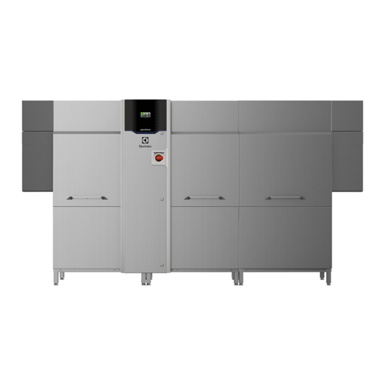
- Page 1 Rack type dishwasher EMRA060 Installation manual * 59566V800- 2020.06 *Original instructions...
- Page 2 Installation diagram EMRA060 right to left 2095 1325 1635...
- Page 3 Installation diagram EMRA060 left to right 2095 1325 1635...
- Page 4 D = Drain outlet ⌀=50mm (external) XI= Pipe inlet for delime EI = Electricity inlet XP= Chemicals probe/sensor EO = Electricity outlet WI = Water inlet G 3/4″ ES = Electrical signal IN/OUT CWI = Cold water inlet G 3/4″ EQ = Equipotential screw U = USB XD= Pipe inlet for detergent...
- Page 5 Foreword The installation, use and maintenance manual (hereinafter Manual) provides the user with information necessary for correct and safe use of the machine (or “appliance“). The following must not be considered a long and exacting list of warnings, but rather a set of instructions suitable for improving machine performance in every respect and, above all, preventing injury to persons and animals and damage to property due to im- proper operating procedures.
-
Page 6: Table Of Contents
Contents A SAFETY INFORMATION ......................... 8 General information ........................8 General safety ..........................8 Personal protection equipment ......................9 Transport, handling and storage ...................... 9 Installation and assembly ......................10 Water connection........................10 Electrical connection ........................10 Parts and accessories ......................... 11 Disposal of packing ........................ - Page 7 First starting ..........................25 H BASIC MACHINE SETUP ........................26 Enter into service menu ....................... 26 User Interface settings menu......................26 Installation settings menu ......................27...
-
Page 8: Asafety Information
SAFETY INFORMATION General information To ensure safe use of the machine and a proper understanding of the manual it is necessary to be familiar with the terms and typographical conventions used in the documentation. The following symbols are used in the manual to indicate and identify the various types of hazards: WARNING Danger for the health and safety of operators. -
Page 9: Personal Protection Equipment
• Machine positioning, installation and disassembly must be carried out by the specialised personnel in conformity with the current safety regulations, regarding the equipment used and the operating procedures. Personal protection equipment Summary table of the Personal Protection Equipment (PPE) to be used during the various stages of the machine's service life. -
Page 10: Installation And Assembly
• Do not push or pull the machine to move it, as it may tip over. Use proper tool to lift the machine. • Machine transport, handling and storage personnel must be adequately instructed and trained regarding the use of lifting systems and personal protection equipment suitable for the type of operation carried out. -
Page 11: Parts And Accessories
• To protect the power supply of the machine against current leakages, install a high- sensitivity manual reset RCD (Residual Current Device), suitable for overvoltage category III. • For protection against indirect contacts (depending on the type of supply provided for and connection of earths to the equipotential protection circuit ) refer to point 6.3.3 of EN 60204-1 (IEC 60204-1) with the use of protection devices that ensure automatic cut-... -
Page 12: Definitions
IPX5 tronics fields. Danger source of possible injury or harm to health. Electrolux Professional spa - Viale Treviso, 15 - 33170 Pordenone (Italy) Hazardous any situation where an operator is situation exposed to one or more hazards. -
Page 13: How To Interpret The Factory Description
This manual is intended solely for consultation by the operator Responsibility and can only be given to third parties with the permission of Electrolux Professional SpA. The Manufacturer declines any liability for damage and malfunctioning caused by: Keeping the manual •... -
Page 14: Type Reference
Machine (cont'd.) Max. current absorbed 86.5 Legal noise level Leq dB(A) LpA:58dB - KpA:1.5dB The noise emission values have been obtained according to EN ISO 11204. Prewash Tank capacity Temperature (min - max) ℃ 40 - 60 Pump power Tank heating element Max. -
Page 15: Characteristics Of Power Supply
Machine with Energy Saving Device (ESD) Max POWER Max Current Model Machine module DR Module module (KW) 47.3 68.3 51.7 74.7 55.8 80.6 MREE PWLE MREEW 55.8 80.6 60.1 86.8 64.3 Suitable for UK & Australia CAUTION For all the additional modules installed later. make sure that the power cable supply is properly sized. -
Page 16: Einstallation And Assembly
CAUTION Install the machine at a distance of not less than 50 mm from the wall so as not to affect correct ventilation internal components. Model Qtot (VDI2052) EMRA060 2000 m... -
Page 17: Positioning
Positioning Polyethylene NOTE! • Outer wrapping Make sure that the room temperature where you • Instructions bag install the machine must be at least 18℃ [64.5℉]. The machine must be taken to the place of installation and the Polypropylene packing base removed only when being installed. •... -
Page 18: Constructional Modifications
The Manufacturer provides for the possibility of connecting the rack-type dishwasher to rack handling systems included in the Electrolux Professional product catalogue, with the possibility of obtaining various configurations. The “EC“ Conformity Declaration provided with the machine also envisages these configurations. -
Page 19: Arrangement For Electrical Connection (Only For Electrolux Rack Handling System Motor Operated)
5. Apply silicone “C“ between the dishwasher and the rack handling system. End Limit Switch End Limit Switch CAUTION Make sure that there are not any water E.12.1 Prearrangement for electrical connection leakages. The machine is pre-configured for the installation of end limit switch. -
Page 20: Electrical Connection
Also, the fans are deactivated when a part of the detergent, rinse aid and descaling agent sug- machine is opened or the emergency switch is pressed, gested by Electrolux Professional. In the Electrolux putting the entire installation is safe conditions. Professional web site, open the “Accessories and If you need to connect external ventilation hood motors, Consumables“... -
Page 21: Rinse Aid Dispenser
E.15.1 Rinse aid dispenser The left or right side panels of the dishwasher have a “T“ injector [⌀=6 mm] for connecting the rinse aid dispenser. To connect the dispenser, carefully carry out the following instructions: • unscrewing the “U“ fitting from the “T“ injector; •... -
Page 22: Rinse Aid Dispenser
Connect the power cable to the equipment: 13 AB 13 BEL • open the door electrical box; 14 AB 14 BEL 15 AB 15 BEL • pass the power cables through hole; 16 AB 16 BEL • connect the power cable to the switch disconnector of the machine;... -
Page 23: Fcontrol Panel Description
Curtains position Appliance curtains Left to right quadruple long (blue) Double long (grey) Single short (grey) Fasten the curtains with the flat part against the hook Right to left Hood curtains Left to right Right to left Single long (grey) Fasten the curtains with the flat part against the hook CONTROL PANEL DESCRIPTION... -
Page 24: Gcommissioning
Pop Up menu Pop Up menu (cont'd.) “Alarm“ menu “Drain and Refill“ menu “Shutdown“ menu “Service“ menu, protected by a password. “Information“ menu COMMISSIONING Preliminary checks, adjustments and 2. prewash 35″ module, if present; operational tests Before starting the machine, check: 1. -
Page 25: Positioning And Fitting Of The Washing And Rinse Arms
4. rinse module. 2. the arms of prewash and wash 35″ module; Right to left 3. the arms of rinse module. Left to right Positioning and fitting of the curtains Positioning and fitting of the washing Make sure all the types of curtains, provided with the machine, are correctly fitted according to that indicated in paragraph and rinse arms “E.18 Fitting curtains“. -
Page 26: Hbasic Machine Setup
IMPORTANT 3. When the display shows the ready status, the dishwasher To guarantee sanitization of the dishes, wash at is ready to work. least 3 empty racks at lowest speed. This allows all the machine to reach the working temperature. Repeat the procedure if the machine is stopped for a long time. -
Page 27: Installation Settings Menu
Set the current date. 10. Set the temperature in Celsius or Fahrenheit [℃ - ℉]. Set Date Temperature °C °F Set “time“ parameters. 11. Set the water level in mm or inch. User Interface settings Water Level Set Date Set Time Set Measurements Units 12. - Page 28 NOTE! 3. Set the “Filter cleaning frequency“. The display shows you On the bottom part of the display, the minimum, the default value. Insert the new value and confirm it. maximum and the default values appears alternately. Installation Settings Please ask to the customer the “Filter cleaning frequency“...
- Page 30 Electrolux Professional SPA Viale Treviso 15 33170 Pordenone www.electroluxprofessional.com...
Need help?
Do you have a question about the EMRA060 and is the answer not in the manual?
Questions and answers