
Related Manuals for Halsey Taylor WM14WQ 1L Series


Summary of Contents for Halsey Taylor WM14WQ 1L Series
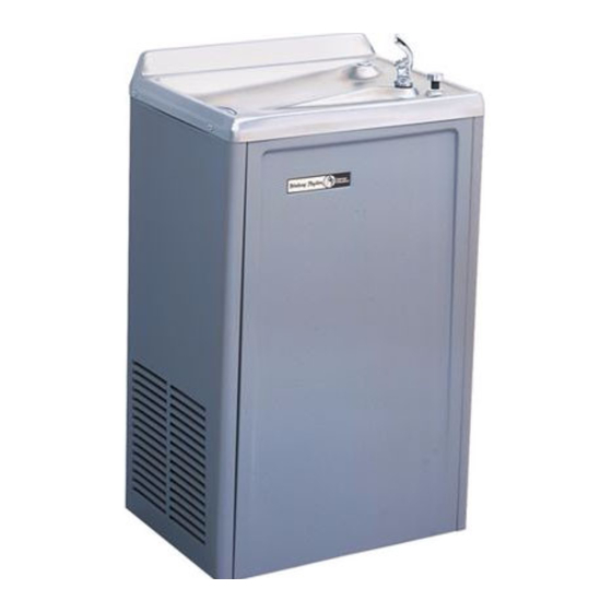
- Page 1 WM14WQ*1L HALSEY TAYLOR OWNERS MANUAL USES HFC-134A REFRIGERANT SEE FIG. 5 1, 32 14,15 2, 3 30, 31,10 FIG. 4 8,9,11 37,38 FIG. 1 PAGE 1 97535C (Rev. H - 6/09)
- Page 2 WM14WQ*1L 97535C (Rev. H - 6/09) PAGE 2...
- Page 3 WM14WQ*1L PUSH BUTTON VALVE ADJUSTMENT STREAM HEIGHT ADJUSTMENT SCREW ADJUST THIS SCREW TO ELIMINATE VALVE LEVER "FREE PLAY" OR CONTINUOUS FLOW FROM BUBBLER FIG. 3 22,26,27 FIG. 4 CORRECT STREAM HEIGHT FIG. 5 PAGE 3 97535C (Rev. H - 6/09)
- Page 4 WM14WQ*1L ITEMIZED PARTS LIST ITEM NO. PART NO. DESCRIPTION WIRING DIAGRAM 51544C Bubbler This drawing is merely for illustrating the 102639931640 Drain Plug components of the electrical system. 160270508640 Strainer Plate 28340C Basin 75561C Fitting-Elbow 3/8 x 3/8 NPT x 90 66506C Evaporator 31513C...
Need help?
Do you have a question about the WM14WQ 1L Series and is the answer not in the manual?
Questions and answers