Advertisement
KSL-E101
INSTALLATION INFORMATION
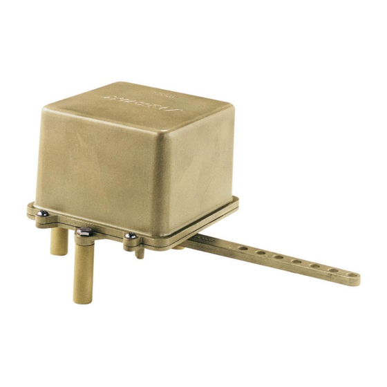
7174 Rudder Angle Feedback Unit
The 7174 rudder angle feedback unit is used in vessels to provide the rudder position feedback signal
for Autopilot, Full follow up control systems and rudder angle indicators. Up to three potentiometers,
three trim pots and four micro switches can be provided with the unit.
Fig. 1 Wiring diagram of potentiometers
Fig. 2 Wiring diagram of micro switches
The lever on the 7174 feedback unit has a series of 5/16" (8 mm) holes at 5/8" (16 mm) intervals for
connecting feedback linkage. The maximum travel of the lever is 44° on either side of travel. To get
the maximum accuracy in performance, the unit is to be installed securely on a flat surface parallel to
and level with the tiller.
Diagram 3: Dimensions of 7174 rudder angle feedback unit
10/2007
Advertisement
Table of Contents

Subscribe to Our Youtube Channel
Related Manuals for Kobelt 7174


Summary of Contents for Kobelt 7174
- Page 1 Fig. 2 Wiring diagram of micro switches The lever on the 7174 feedback unit has a series of 5/16” (8 mm) holes at 5/8” (16 mm) intervals for connecting feedback linkage. The maximum travel of the lever is 44° on either side of travel. To get the maximum accuracy in performance, the unit is to be installed securely on a flat surface parallel to and level with the tiller.
- Page 2 4. Secure the fasteners on both ends. 5. Ensure there is no obstruction in the movement of both tiller and feedback unit arms. 6. Calibrate the 7174 feedback unit for its full range of lever arm travel after installation. 10/2007...
Need help?
Do you have a question about the 7174 and is the answer not in the manual?
Questions and answers