Kobelt 7174 Owner's Operation, Installation & Maintenance Manual
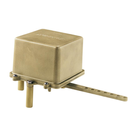
Rudder feedback unit
Hide thumbs
Also See for 7174:
- Installation information (2 pages) ,
- Owner's operation, installation & maintenance manual (44 pages)

Subscribe to Our Youtube Channel
Related Manuals for Kobelt 7174


Summary of Contents for Kobelt 7174
- Page 1 7174 Rudder Feedback Unit Owner’s Operation, Installation & Maintenance Manual (Rev A)
- Page 2 7174 Rudder Feedback Unit Kobelt Manufacturing Co. Ltd. NOTES RECORD DATA BEFORE INSTALLATION FOR FUTURE REFERENCE Model #: Serial #: Date of Purchase: Date of Installation: Rev A mnl7174.docx 2 of 21...
-
Page 3: Table Of Contents
7174 Rudder Feedback Unit Kobelt Manufacturing Co. Ltd. ABLE OF ONTENTS Introduction ......................4 Contact ........................4 Compliant Use ......................4 Copyrights & Trademarks ................... 4 Safety ........................5 Safety Alerts ....................... 5 Notice to Installer ....................... 5 Product Hazards ......................6 Product Description .................... -
Page 4: Introduction
Kobelt reserves the right, without notice, to change the design, or construction, of any products and to discontinue or limit distribution of any products. Kobelt also reserves the right to change, or update, without notice, any technical information contained within this document. -
Page 5: Safety
• Do not carry out any modifications to the product. • Only use authentic Kobelt spare parts. • Observe all local regulations, directives and laws during the installation of this product. • All installation, commissioning, and maintenance work must only be conducted by qualified personnel. -
Page 6: Product Hazards
7174 Rudder Feedback Unit Kobelt Manufacturing Co. Ltd. RODUCT AZARDS Disconnect Power: Turn off power at distribution panel before beginning installation to protect installer from electrical hazards. Voltage and Current Compatibility: Confirm that the power source is compatible with the maximum voltage and current ratings of is product variant. -
Page 7: Product Description
RODUCT ESCRIPTION The Kobelt 7174 Rudder Feedback Unit (RFU) can be configured to have up to four potentiometers and two rudder end stop switches per side. It can be used as an input to Full Follow Up (FFU) electronic steering systems, autopilots, and rudder angle indicators. -
Page 8: Technical Specifications
7174 Rudder Feedback Unit Kobelt Manufacturing Co. Ltd. ECHNICAL PECIFICATIONS Table 1: 7174 Technical Data – Standard Variants MODEL 7174 KOBELT PART # 7174-A 7168-B POTENTIOMETER 1kΩ 2x 1kΩ MAX. POTENTIOMETER POWER SWITCH CONTACTS 2x DPDT 2x DPDT CONTACT RATINGS 250VAC/24VDC –... -
Page 9: Installation
7174 Rudder Feedback Unit Kobelt Manufacturing Co. Ltd. NSTALLATION ECHANICAL Ideally, the Rudder Feedback Unit should be mounted as close as possible to the tiller arm. Excessive lengths of connecting rods will lead to flexing and inaccuracies in the reported rudder position. -
Page 10: Electrical
Placed as to protect external electrical cable from damage. The cable gland locations are shown in Error! Reference source not found. and the internal wire connections are shown in Figure 3: 7174 Potentiometer Wiring Diagram and Figure 4: 7174-XG Internal Wiring Diagram respectively. - Page 11 Wire Name Colour Gauge Function FFU potentiometer power supply POT+ White 18AWG connection. POT WIPER Green 18AWG FFU potentiometer signal connection. POT- Black 18AWG FFU potentiometer ground connection. Figure 3: 7174 Potentiometer Wiring Diagram Rev A mnl7174.docx 11 of 21...
- Page 12 7174 Rudder Feedback Unit Kobelt Manufacturing Co. Ltd. Figure 4: 7174-XG Internal Wiring Diagram When wiring the rudder end stop switches directly to the steering solenoid valves, it is recommended to place a 1N4007 protection diode across the coil terminals.
-
Page 13: Commissioning
Ensure that the rear cover is installed and secured before powering on the 7174. • Confirm that the electrical connections to the 7174 have been made. • Confirm that port and starboard rudder movements are displayed correctly at the rudder angle indicators. -
Page 14: Maintenance
Position the rudder to the desired trip position. Remove the RFU cover. Locate the relevant switch trip cam (see Figure 1: 7174 Overview Diagram). Loosen the two screws and rotate the cam until the switch just trips and secure the two screws. -
Page 15: Recommended Spare Parts
When purchasing replacement parts refer to Appendix B: Parts List at the back of this manual for Kobelt component Part Numbers. It is recommended that any required service work on a Kobelt product be performed by a factory authorized service representative. -
Page 16: Troubleshooting
If you encounter problems with the operation of your product, please refer to the trouble- shooting suggestions before contacting Kobelt for assistance. If the steps below do not resolve your issue, please reach out either Kobelt directly or our Dealers in your area. Table 4: Common Solutions... -
Page 17: Warranty
If any part is found to be defective, Kobelt will replace said part FOB the Kobelt factory provided that any such defective part is returned by the Buyer with freight and applicable forwarding charges prepaid by the Buyer. -
Page 18: Appendix A: Installation Dimensions
7174 Rudder Feedback Unit Kobelt Manufacturing Co. Ltd. A: I PPENDIX NSTALLATION IMENSIONS Rev A mnl7174.docx 18 of 21... -
Page 19: Appendix B: Parts List
7174 Rudder Feedback Unit Kobelt Manufacturing Co. Ltd. 10 A B: P PPENDIX ARTS Figure 5: 7174-CP Parts Diagram Rev A mnl7174.docx 19 of 21... - Page 20 7174 Rudder Feedback Unit Kobelt Manufacturing Co. Ltd. ITEM QTY. PART NUMBER DESCRIPTION 7174-0001 HOUSING 7174-0002 BOTTOM PLATE; RUDDER FEED BACK UNIT 7174-0003 LEVER; RUDDER FEEDBACK UNIT 7174-0009 SPACER, BRASS 7174-0010 SHAFT 6001-0248 CABLE GLAND; M16 X 1.5, .197-.394 CABLE, PA6, BLACK...
- Page 21 Kobelt Manufacturing Co. Ltd. 8238 129th Street Surrey, British Columbia, Canada, V3W 0A6 Sales Tel: +1-604-572-3935 Fax: +1-604-590-8313 Email: sales@kobelt.com Website: www.kobelt.com Made in Canada / Printed in Canada...
Need help?
Do you have a question about the 7174 and is the answer not in the manual?
Questions and answers