Table of Contents
Advertisement
Quick Links
Advertisement
Table of Contents

Related Manuals for Indu-Sol PROmesh B8+F


Summary of Contents for Indu-Sol PROmesh B8+F
- Page 2 Indu-Sol GmbH Blumenstraße 3 042626 Schmölln Tel.: +49 (0)34491 / 580 0 Fax: +49 (0)34491 / 580-499 E-mail: info@indu-sol.com Web: https://www.indu-sol.com Our technical support team can be reached at +49 (0)34491 / 58 18 14, on workdays between 7:30 - 16:30 (CET).
-
Page 3: Revision Overview
No claims can be derived from the information, figures and descriptions in this documentation. Any reproduction, further processing and translation of this document or extracts thereof require the written consent of Indu-Sol GmbH. All rights under copyright law are expressly reserved by Indu-Sol GmbH. W A R N U N G Commissioning and operation of this unit may only be carried out by qualified personnel. -
Page 4: Table Of Contents
Table of contents Table of contents Revision overview Table of contents General information Overview of the PROmesh P8+F - Scope of Functions Scope of delivery Safety instructions Connections and status indicators on the unit Device connections Installation Installation Power supply connection and error relay LED displays Reset button Network integration &... - Page 5 Table of contents Switching Port configuration Quality of Service VLAN Bandwidth control Link aggregation Redundancy RSTP MSTP 3.10 System configuration Unit information IP configuration Password Time setting SNMP Access time Backup Restoration Firmware update Factory settings Restart 3.11 Support 3.12 Troubleshooting tips Technical specification en PROmesh P8+F - User Manual...
-
Page 6: General Information
General information 1 General information Please read this document thoroughly from beginning to end before you start installing and commissioning the device. 1.1 Overview of the PROmesh P8+F - Scope of Functions PROmesh P8+F is an industrial Ethernet switch with management and PROFINET functionality that can be configured easily and conveniently via a web application. -
Page 7: Scope Of Delivery
General information 1.2 Scope of delivery The scope of delivery includes the following individual parts: PROmesh P8+F 5-pole pluggable terminal block, 2.5mm² (power supply and alarm contact) User Quick Start Guide (Hardcopy) SD card, for backup and update Please check the contents of your delivery for completeness before commissioning. -
Page 8: Connections And Status Indicators On The Unit
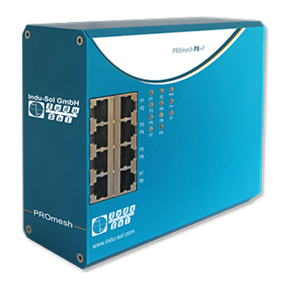
Connections and status indicators on the unit 2 Connections and status indicators on the unit 2.1 Device connections Power supply, alarm contact and reset Status LEDs Reset X1 Data ports 8x RJ45 24 V Potential-free switching contact FE Connection SD card holder on the rigth side of the switch Figure 1: Unit connections PROmesh P8+F - User Manual... -
Page 9: Installation
Connections and status indicators on the unit 2.2 Installation The PROmesh P8+F is designed for individual use in control cabinets of various types and can be mounted on a standard 35mm DIN rail. Only use the existing top-hat rail fastening for mounting the unit or, if necessary, purchase appropriate spare parts to ensure sufficient electrical contact and the mechanical load capacity of the unit. -
Page 10: Power Supply Connection And Error Relay
Connections and status indicators on the unit Figure 3: Mounting and dismounting on the top-hat rail Do not mount the PROmesh P8+F switches directly next to devices that generate strong electromagnetic interference fields, e.g. transformers, contactors, frequency converters, etc. Do not mount the PROmesh P8+F switches directly next to heat-generating devices and protect the switch from direct sunlight to avoid unwanted heating. - Page 11 Connections and status indicators on the unit The listed labels are also included on the terminal block supplied. A potential-free error relay contact (break contact) is located at the OUT terminals inside the unit. The relay serves as an alarm receiver and can be linked to various alarm triggers in the software. Depending on the configuration, the relay contact then opens, for example, in the event of a power failure or a change in the status of the port.
-
Page 12: Led Displays
Connections and status indicators on the unit 2.5 LED displays There are four diagnostic LEDs on the front panel of the switch. In addition, each of the 8 data ports has a status LED. The LEDs show the most important diagnostic information about the device and connection status of the PROmesh P8+F in your PROFINET network (see Table 1). -
Page 13: Network Integration & Commissioning
Use twisted pair cables of category 5 (Cat 5) or higher with a maximum cable length of up to 100 m to connect your PROmesh P8+F via the existing RJ-45 data ports. To improve the shielding, we recommend the PROFINET RJ45 connectors from Indu-Sol. PROmesh P8+F - User Manual... -
Page 14: Network Topologies & Redundancy
Connections and status indicators on the unit 2.8 Network topologies & redundancy By using different protocols, the devices of the PROmesh product family can be used in redundant networks, such as meshed networks or rings, in addition to being used in star-shaped switched Ethernet networks. - Page 15 Connections and status indicators on the unit Figure 6: PROmesh P8+F in a ring-shaped network PROmesh P8+F - User Manual...
-
Page 16: Web Application
You can easily set your intended user addresses with the Indu-Sol ServiceTool. This is included in the scope of delivery or is available for free download via the following link: https://sdx.indu-sol.com/s/CtYtsHNW73Z3KCa... -
Page 17: System Login
Web application 3.2 System Login 1. Start a web browser on your computer. 2. Enter the IP address of the PROmesh P8+F switch you are using in the address line of the web browser and confirm your entry with the Enter key. 3. -
Page 18: Start
Web application There is no communication at the respective port. Either no device is connected (possibly also line interruption) or no telegram traffic can be detected (serious disturbance in the network) or the devices are no longer communicating. 3.4 Start After successful login, you will be taken to the main overview with the information bar, in which the unit name, installation location and IP address can be seen. - Page 19 Web application Message window Port statistics Leakage current Figure 8: Start PROmesh P8+F - User Manual...
-
Page 20: System Information
Web application 3.5 System information In addition to the unit information, an overview of the activated or deactivated protocols and functions is displayed under this menu item. By selecting the respective edit button, you can switch directly to the corresponding protocols and functions in order to make settings there. Figure 9: Status and diagnosis 3.6 Diagnosis The Diagnostics page provides an overview of the status of configured alarm triggers (alarm trigger... - Page 21 Web application Figure 10: Quality value Information Bar Chart 3 values are displayed per bar. The grey coloured part of each bar shows its maximum value. The colour-saturated part, which is bordered by a black line, shows the current quality value. The coloured saturated part, which is bordered by a line with 2 arrows, shows the worst quality value of the connection so far.
-
Page 22: Leakage Current
Web application Miscellaneous The threshold value, which colours the bar yellow and recommends checking the connection, can be adjusted by the user. It is not recommended to set the threshold below 30 %. In the Alarms menu, alarms can be defined for the line quality value, which send messages via relay, SNMP, PROFINET or e-mail if the value falls below a threshold. -
Page 23: Network Statistics
Web application Network statistics The Port Statistics page provides information about the data traffic of the individual ports. This information is useful for diagnostic purposes or in case of network problems. In the main overview of the port statistics, the following information is provided for each port: ... -
Page 24: Neighbourhood Detection (Lldp)
Web application Number of all packages Total bytes received Number of fragments received The line Packets up to bytes provides information about the number of packets in different sizes. Here the number of received packets up to 63, 127, 255, 511, 1023, or 1518 bytes in size is recorded. In addition, parcel collisions are recorded and post: ... -
Page 25: Port Mirroring
Web application Port Mirroring Port mirroring is a method of simultaneously directing the traffic of one port (source) to a second port (destination) in networks and thus checking it. This means that the received and sent packets of the source port are duplicated to the monitoring port. - Page 26 Web application The alarms created can be linked to one or more alarm receivers, these include: Error relay SNMP traps E-mail addresses PROFINET (only configurable via configuration software) If one of the created alarms is detected and triggered, the software forwards the event to the corresponding alarm receiver and also documents the event as a syslog message.
-
Page 27: Messages
Web application Add and edit alarm receivers By clicking on the button with the "+" symbol, new alarm receivers can be added. The relay is already present as an alarm receiver and cannot be deleted, but only linked to alarm triggers. In addition to this, the recipients e-mail, SNMP and PROFINET can also be selected. -
Page 28: Profinet
Web application Please check whether there is enough memory available on the SD card and whether the messages are saved in a file. Resetting the entries The button "Delete entries" removes all entries from the table. The time at which the entries were deleted can then be viewed as the first entry with the description "Logfile reset by User!"... -
Page 29: Port Configuration
Web application Port configuration The table provides an overview of the current configuration of the individual ports. The columns Enabled, Autonegotiation, Flow Control and Designation are also editable. The page is regularly updated and reloaded. Figure 14: Port configuration The columns in detail: ... -
Page 30: Quality Of Service
Web application Flow control: Flow control ensures that if a port is overloaded, the received data packets are ignored and the connected device is signalled to stop sending. Designation: In this column you can give the ports a name. The names are displayed throughout the configuration and facilitate the selection of the correct settings as well as diagnosis in the event of an error. -
Page 31: Vlan
Web application (NC,7-high). Assign the COS priorities to the four queues of the switch as you need it in your application. Type based (TOS): TOS uses a Differentiated Services Code Point (DSCP) data field in the IP header of the packets, which can have up to 64 different priorities. As with COS, you can use these priorities to prioritise, for example, real-time control data, Voice over IP (VoIP) or audio data over normal data transfer. - Page 32 Web application Untagged (configurable in the VLANs tab): Ports that are stored as untagged in a VLAN can receive and forward packets of this VLAN ID. A port can be stored in several VLANs as an untagged port if the devices connected to this port are to communicate with several VLANs. ...
- Page 33 Web application Figure 16: Add new VLAN The Ports tab gives you an overview of the current configurations. Furthermore, you can determine the PVID. Figure 17: VLAN overview PROmesh P8+F - User Manual...
-
Page 34: Bandwidth Control
Web application Bandwidth control Bandwidth control allows you to enforce bandwidth limits on a port. You can set different send and receive rates for each port (incoming / outgoing packets) and apply them to specific packet types. The tabular overview offers you the following settings: ... - Page 35 Web application Static You can add a new link aggregation group via the "+" button. You can then: Group ID: Each link aggregation group has an ID (1-14). Type: specifies whether static or dynamic link aggregation is used ...
-
Page 36: Redundancy
Web application 3.9 Redundancy This page provides you with an overview of the available redundancy protocols and their status. It is not possible for several redundancy protocols to run at the same time, so only one can be activated. With the help of the edit buttons, you can access the protocols and carry out the configuration there. -
Page 37: Rstp
Web application This unit operates as: Please specify whether the unit is to act as a manager or as a client. Please note that only one manager may be used per ring. RSTP The Rapid Spanning Tree Protocol (RSTP) is a standardised method to manage mixed structures, including a ring, in the network. - Page 38 Web application Figure 18: Device settings RSTP Note: Follow the rule to configure Forward Delay, Maximum Age and Hello Time: 2 * (Forward Delay Time - 1) >= MaxAge >= 2 * (Hello Time + 1). Recommended procedure: Select a value for the "Hello Time" and calculate with the formula 2 * (Hello Time + 1) according to the rule given above to obtain the lower limit of the Maximum Age.
- Page 39 Web application Port settings Set the following port-related settings per port: Port: You can configure all ports individually. RSTP on: For each port, select whether the Rapid Spanning Tree Protocol should be activated on this port or not. ...
-
Page 40: Mstp
Web application MSTP Instance configuration In this menu you can create multiple spanning tree instances. This allows you to create a separate spanning tree for each VLAN. The following settings are required for this: Instance ID: Select the Multiple Spanning Tree Instance ID here. This ID must be identical for all switches that are to belong to the same spanning tree. -
Page 41: Unit Information
Web application Figure 19: System configuration Unit information The Unit Information page allows you to assign a unique unit name, installation location and contact person to the unit. Device name: This name corresponds to the PROFINET name and is assigned by means of DCP. -
Page 42: Ip Configuration
DHCP server. Since the unit has now received a new IP address, it can no longer be reached via the default IP. Please contact your network administrator or use an appropriate tool (Indu-Sol ServiceTool) to obtain the new IP address. Manual If your network does not have a DHCP server or you want to make the settings manually, deactivate the "automatic (DHCP)"... -
Page 43: Password
Web application Password On this page, the preset default password for the users Admin and User can be changed. The user names and rights of the administrator and the user are fixed and cannot be changed. Form fields New password: Please enter the password you have set for the previously selected user in this field. -
Page 44: Snmp
Web application Figure 20: Time server Automatic (SNTP) SNTP Server: Store the IP address of the time server. It is possible to store a second time server as redundancy. Update interval: Here you can determine the cycle in which the device time is synchronised with the time server. -
Page 45: Access Time
Web application Remove: You can mark the community strings to be deleted and then remove them with the "Delete" button. Create SNMP access To create a new community string, click on the "Add" button. The following parameters are required: ... -
Page 46: Backup
SD card: The backup file is on an SD card and is restored from there. Firmware update Here you can update the firmware of the device. Please only use firmware versions that you have received from Indu-Sol and that have been developed for the PROmesh switches. PROmesh P8+F - User Manual... - Page 47 Web application Figure 21: Fimware update The firmware file is either provided by a TFTP server or loaded onto the unit via upload or SD card. Before updating, check that you have selected the correct firmware image. Upload: The firmware update is located on the computer currently in use and is transferred from there to the unit.
-
Page 48: Factory Settings
Alternatively, you can switch the two supply voltages of the switch off and on again and thus perform a hardware reset. 3.11 Support In the Support section you will find all relevant contact information for Indu-Sol Licence information The linked license.txt file contains information regarding the "open source software" used. -
Page 49: Technical Specification En
Technical specification en 4 Technical specification en Network connections 8 x up to 1 Gbit/s RJ45 Power supply 12 V ... 48 V DC power supply Power consumption Maximum 8 W Dimensions (HxWxD) 130 mm x 150 mm x 60 mm Weight 0,9 kg Housing...
Need help?
Do you have a question about the PROmesh B8+F and is the answer not in the manual?
Questions and answers