Table of Contents
Advertisement
Quick Links
Advertisement
Table of Contents

Related Manuals for Indu-Sol PROmesh P9+


Summary of Contents for Indu-Sol PROmesh P9+
- Page 2 Indu-Sol GmbH Blumenstraße 3 D-042626 Schmölln Phone: +49 (0)34491 / 580 0 +49 (0)34491 / 580-499 Fax: Email: info@indu-sol.com Web: https://www.indu-sol.com Our technical support team is available at +49 (0)34491 / 58 18 14, weekdays between 7:30 – 16:30 (CET).
-
Page 3: Revision Overview
No claims can be derived from the specifications, figures, or descriptions in this documentation. Any kind of reproduction, subsequent editing, or translation of this document, as well as excerpts from it, requires the written consent of Indu-Sol GmbH. All rights under copyright law are expressly reserved for Indu-Sol GmbH. -
Page 4: Table Of Contents
Table of contents Table of contents Revision overview Table of contents General information Overview of the PROmesh P9+ – function scope Scope of supply Safety notices Connections and status indicators on the device Device connections Installation Mounting Connection of power supply and error relay LED displays Reset button Network integration &... - Page 5 Table of contents Switching Port configuration Quality of service VLAN Bandwidth control Link aggregation Redundancy RSTP MSTP 3.10 System configuration Device information IP configuration Password Time setting SNMP Access time Backup Recovery Firmware update Factory settings Reboot 3.11 Support 3.12 Troubleshooting advice Technical specifications PROmesh P9+–...
-
Page 6: General Information
General information 1 General information Please read this document thoroughly from start to finish before you begin installing the device and putting the device into operation. – function scope 1.1 Overview of the PROmesh P9+ PROmesh P9+ is an industrial Ethernet switch with management and PROFINET functions that can be configured easily and conveniently via a web application. -
Page 7: Scope Of Supply
General information 1.2 Scope of supply The scope of supply comprises the following individual parts: PROmesh P9+ 7-pin pluggable terminal block, 2.5 mm² (power supply and alarm contact) User quick start guide (hardcopy) SD card, for backup and update Check that the content of your delivery is complete before commissioning. -
Page 8: Connections And Status Indicators On The Device
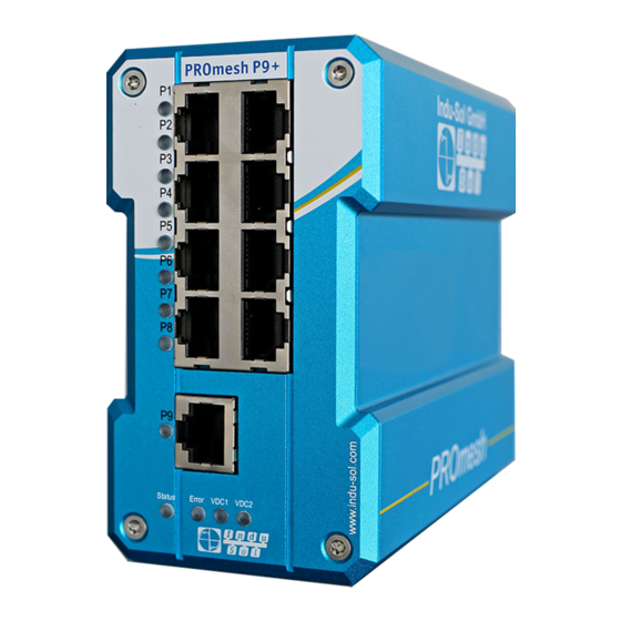
Connections and status indicators on the device 2 Connections and status indicators on the device Device connections Power supply and alarm contact FE connection Potential-free X1 data ports switching contact 24 V 9x RJ45 Reset card holder Status LEDs Figure 1: Device connections PROmesh P9+–... -
Page 9: Installation
Connections and status indicators on the device 2.2 Installation The PROmesh P9+ is designed for individual use in control cabinets of various types and can be mounted on a standard 35 mm DIN top-hat rail. Only use the existing top-hat rail fastening for mounting the device or, if necessary, purchase appropriate spare parts to ensure sufficient electrical contact and the mechanical load capacity of the device. -
Page 10: Connection Of Power Supply And Error Relay
Connections and status indicators on the device Figure 3: Mounting and dismounting on the top-hat rail Do not mount the PROmesh P9+ switches directly adjacent to any devices that generate strong electromagnetic interference fields, such as transformers, contactors, frequency converters, etc. Do not mount the PROmesh P9+ switches directly adjacent to any heat-generating devices and... - Page 11 Connections and status indicators on the device There is a potential-free error relay contact (NC contact) at the OUT terminals inside the unit. The relay serves as an alarm receiver. It can be linked to various alarm triggers in the software. The relay contact then opens, for example, in case of a power outage or a change in the status of the port depending on the configuration.
-
Page 12: Led Displays
Connections and status indicators on the device 2.5 LED displays There are four diagnostic LEDs on the front panel of the switch. Each of the 9 data ports also has a status LED. The LEDs display the most important diagnostic information about the device and connection status of the PROmesh P9+ in your PROFINET network (see Table 1). -
Page 13: Network Integration & Commissioning
Connect your PROmesh P9+ via the existing RJ-45 data ports using twisted pair cables of category 5 (Cat 5) or higher with a maximum cable length of up to 100 m. We recommend the PROFINET RJ45 connectors from Indu-Sol to improve the shielding. PROmesh P9+– User Manual... -
Page 14: Network Topologies & Redundancy
Connections and status indicators on the device 2.8 Network topologies & redundancy The devices of the PROmesh product family can be used in redundant networks, such as meshed networks or rings, via different protocols in addition to being used in star-shaped switched Ethernet networks. Network topologies Classical Ethernet star structures (see Figure 5) can be linked to the PROmesh P9+... - Page 15 Connections and status indicators on the device Figure 6: PROmesh P9+ in a ring-shaped network PROmesh P9+– User Manual...
-
Page 16: Web Application
You can easily set your intended user addresses with the Indu-Sol ServiceTool. This is part of the scope of delivery or can be downloaded for free via the following link: https://sdx.indu-sol.com/s/CtYtsHNW73Z3KCa... -
Page 17: System Login
Web application 3.2 System login 1. Launch a web browser on your computer. 2. Enter the IP address of the PROmesh P9+ switch you are using into the address line of the web browser and confirm your entry with the Enter key. 3. -
Page 18: Start
Web application There is no communication at the respective port. Either no device is connected (potentially also at line interruption) or no telegram traffic can be detected (serious fault in the network) or the devices no longer communicate. 3.4 Start Successful login will lead to the main overview with the information bar, where the device name, the installation location, and the IP address are displayed. - Page 19 Web application Message window Port statistics Leakage current Figure 8: Start PROmesh P9+– User Manual...
-
Page 20: System Information
Web application 3.5 System information An overview of the enabled or disabled protocols and functions is displayed under this menu item in addition to the device information. You can switch directly to the corresponding protocols and functions in order to make settings there by selecting the respective Edit button. - Page 21 Web application Figure 10: Quality value Information bar chart 3 values are displayed per bar. The grey part of each bar shows its maximum value. The lesser coloured part, bordered by a black line, shows the current quality value. The colour-saturated part, which is bordered by a line with 2 arrows, shows the worst quality value of the connection so far.
-
Page 22: Leakage Current
Web application Leakage current Leakage current monitoring (Figure 11) permits permanent recording and evaluation of the sum of all shield currents of the PROFINET lines that are discharged via the device into the equipotential bonding system. The associated spectrum with the respective frequency components is specified for this purpose, in addition to the current value. - Page 23 Web application Figure 12: Port statistics Resetting the values The upper right part of the web interface contains the “Delete counter” button. The values of the table can be reset with this button. Detailed port statistics The size of the individual packets is recorded statistically up to various threshold values in the statistics details (up to 64, 127, 255, 511, 1023, or 1518 bytes).
-
Page 24: Neighbourhood Detection (Lldp)
Web application Late (a collision that occurs after more than 512 bits) Total . Such collisions and the associated data loss always occur when several subscribers want to send simultaneously on one medium. Neighbourhood detection (LLDP) The Link Layer Discovery Protocol (LLDP) is a vendor-independent layer-2 protocol that provides the ability to exchange information (addresses, names, and descriptions) between neighbouring devices. -
Page 25: Alarm Trigger
Web application Port and port name: All ports are displayed here in order to select a destination port and one or more source ports. Destination port: If port mirroring is enabled, select a port on which to mirror the data. The mirrored packets can be forwarded to exactly one destination port. - Page 26 Web application Figure 13: Alarm trigger The configured alarm assignments are displayed in lists with consecutive ID. Alarm triggers with assigned receivers Alarm receivers with associated triggers Add and edit alarm triggers New alarms and messages can be added by clicking on the button with the “+” symbol. If alarms are already present, the user has the option of editing or deleting them using a button.
-
Page 27: Messages
Web application The user can specify an email address and an SMTP (Simple Mail Transfer Protocol) server when using the email function. The device sends an email to the user if there is an alarm. Authentication can be enabled as an option. The required access data must be entered for this purpose. -
Page 28: Profinet
Web application 3.7 PROFINET The abbreviation Profinet means Process Field Network. It refers to the open Industrial Ethernet standard for automation. The device is developed as a Profinet IO device for connection of decentralised peripherals to a Profinet controller. The device supports conformance Class B. This page offers the option of making port settings for DCP and downloading the configuration file. - Page 29 Web application Figure 14: Port configuration Details on the columns: Port: Specifies the port number, also marked on the housing. Enabled: The individual ports can be enabled or disabled. This specifies whether a port can be used or not. ...
-
Page 30: Quality Of Service
Web application Quality of service Quality of service (QoS) includes all procedures that influence the data flow in the device. With the assignment to queues with different priorities, certain user data can be treated preferentially. For example, real-time data, control data, audio or video data may be preferred over file transfers. The switch supports eight different queues that are processed with different priorities. -
Page 31: Vlan
Web application Class of service only: Priorities are based solely on the class of service data field of the packets. Type of service only: Priorities are based solely on the type of service data field of the packets. Class of service first: In this variant, priorities are determined first by COS, then (if necessary) by TOS, and finally by port. -
Page 32: Bandwidth Control
Web application The management VLAN: The switch itself can be reached via the management VLAN. If the switch is parameterized in a PROFINET controller, an EtherNet/IP scanner or another management software, then it must be ensured that the management VLAN is located in the same VLAN as the scanner/controller/software. -
Page 33: Link Aggregation
Web application Broadcast & multicasts: The set limits apply to all broadcast and multicast packets (to all or multiple devices on the network). Broadcast, multicast & unknown unicasts: The limits apply to all broadcast, multicast, and unknown unicast packets (to one subscriber). ... -
Page 34: Redundancy
Web application Group ID: This setting is relevant if you want to apply static link aggregation. Combine ports into one group for this by entering the same group ID. This setting will not be required for dynamic link aggregation. ... -
Page 35: Rstp
Web application Ring configuration Please note that the ring must not be physically closed until MRP is fully configured. One device per ring must be configured as manager. The other devices must be configured as clients. The following settings are required for MRP: ... - Page 36 Web application Bridge priority: This value is used for negotiating the root bridge. The bridge with the lowest value has the highest priority and is chosen as the root bridge. The value must be between 0 and 61440 and a multiple of 4096. ...
- Page 37 Web application Port settings Set the following port-related settings per port: Port: You can configure each ports individually. RSTP on: For each port, select whether or not to enable the Rapid Spanning Tree Protocol on that port. Status: Displays the current status of each port.
-
Page 38: Mstp
Web application Figure 17: Port settings Click Apply to apply the settings after you have set the respective parameters. MSTP Instance configuration You can create Multiple Spanning Tree instances in this menu. This permits creation of a separate spanning tree for each VLAN. The following settings are required for this: ... -
Page 39: System Configuration
Web application Enforcing: When enabled, the port is configured as an edge port by default. Auto: The port is not configured as an edge port by default. 3.10 System configuration The system configuration page displays IP address settings, time settings, access options to the device, and general device information. -
Page 40: Ip Configuration
Apply button. The device can no longer be reached via the default IP because now has a new IP address. Please contact your network administrator or use an appropriate tool (Indu-Sol ServiceTool) to obtain the new IP address. Manual If your network does not have a DHCP server or you want to make the settings manually, disable the “automatic (DHCP)”... -
Page 41: Password
Web application Please check the settings carefully to avoid problems with duplicate IP addresses. The format of the IP address, the subnet mask and the gateway must be entered in decimal notation. Password On this page the default password for the users Admin and User can be changed. The usernames and rights of the administrator and the user are fixed and cannot be changed. -
Page 42: Snmp
Web application Figure 19: Time server Automatically (SNTP) SNTP Server: Store the IP address of the time server. It is possible to store a second time server as redundancy. Update interval: You can determine the cycle in which the device time is synchronised with the time server here. -
Page 43: Access Time
Web application Read only: The community string allows read-only access. Read and write: The community string allows read and write access. Delete: You can mark the community strings to be deleted and then remove them with the “Delete”... -
Page 44: Backup
SD card: The backup file is stored on an SD card and is restored from there. Firmware update Here you can update the firmware of the device. Please only use firmware versions that you have received from Indu-Sol and that have been developed for the PROmesh switches. PROmesh P9+– User Manual... - Page 45 Web application Figure 20: Firmware update The firmware file is either provided by a TFTP server, uploaded to the device, or placed on an SD card. Before updating, check that you have selected the correct firmware image. Upload: The firmware update is located on the computer currently in use and is transferred from there to the device.
-
Page 46: Factory Settings
You can also turn both power supply voltages of the switch off and on again to perform a hardware reset. 3.11 Support The support section contains all relevant contact information for Indu-Sol License information The linked license.txt file contains information regarding the “Open Source Software” used. - Page 47 Web application PROmesh P9+– User Manual...
-
Page 48: Technical Specifications
Technical specifications 4 Technical specifications Network connections 9 x up to 1 G bit/s RJ45 Power supply 12 V ... 48 V DC redundant power supply Power consumption Maximum 8 W Dimensions (HxWxD) 110 mm x 60 mm x 131 mm Weight 0.9 kg Housing...