
Subscribe to Our Youtube Channel
Related Manuals for Lanner HTCA-E400

Summary of Contents for Lanner HTCA-E400
- Page 1 Telecom Datacenter Appliances HTCA-E400 HMB-E100/HMB-E200/HLM-E110 User Manual Version: 1.1 Date of Release: 2023-02-20...
- Page 2 - assumed to be qualified in the servicing of computer equipment, such as professional system integrators, or service personnel and technicians. The latest version of this document can be found on Lanner’s official website, available either through the product page or through the Lanner Download Center page with a login account and password.
- Page 3 HTCA-E400 User Manual Taiwan Corporate Headquarters China Lanner Electronics Inc. Beijing L&S Lancom Platform Tech. Co., Ltd. 7F, No.173, Sec.2, Datong Rd. Guodong LOFT 9 Layer No. 9 Huinan Road, Xizhi District, New Taipei City 22184, Huilongguan Town, Changping District, Beijing...
- Page 4 HTCA-E400 User Manual This document is copyrighted © 2023. All rights are reserved. The original manufacturer reserves the right to make improvements to the products described in this manual at any time without notice. No part of this manual may be reproduced, copied, translated or transmitted in any form or by any means without the prior written permission of the original manufacturer.
- Page 5 HTCA-E400 User Manual This equipment has been tested and found to comply with the limits for a Class A digital device, pursuant to Part 15 of the FCC Rules. These limits are designed to provide reasonable protection against harmful interference when the equipment is operated in a commercial environment. This equipment generates, uses, and can radiate radio frequency energy and, if not installed and used in accordance with the instruction manual, may cause harmful interference to radio communications.
- Page 6 The installation of this product must be performed by trained specialists; otherwise, a non-specialist might create the risk of the system’s falling to the ground or other damages. Lanner Electronics Inc. shall not be held liable for any losses resulting from insufficient strength for supporting the system or use of inappropriate installation components.
- Page 7 HTCA-E400 User Manual L’équipement électrique génère de la chaleur. La température ambiante peut ne pas être adéquate pour refroidir l’équipement à une température de fonctionnement acceptable sans circulation adaptée. Vérifiez que votre site propose une circulation d’air adéquate. Vérifiez que le couvercle du châssis est bien fixé. La conception du châssis permet à l’air de refroidissement de bien circuler.
- Page 8 Package Content ......................... 10 Ordering Information ......................... 10 Available Blades .......................... 10 Optional Accessories ........................11 System Specifications ......................... 11 HTCA-E400 Front Panel ......................12 HTCA-E400 Rear Panel ........................ 12 Package Content ......................... 13 Ordering Information ......................... 13 Optional Accessories ........................13 HMB-E100 System Specifications ....................
- Page 9 HMB-E100 & HMB-E200: Installing Disk Drives (Optional) ............32 HMB-E200: Installing the GPU graphic card (Optional) ............. 33 HLM-E110: Installing Precision Time Card (Optional) ..............35 HTCA-E400: Installing/Accessing the Compute Sled/Switch Sled ..........36 HTCA-E400: Replacing Power Supply Units ................37 Warranty Policy .......................... 64...
-
Page 10: Key Features
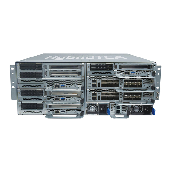
HTCA-E400 User Manual The HTCA-E400, a carrier-grade Open Edge Server, powered by 3rd Gen Intel Xeon Scalable Processors (codenamed Ice lake) with built-in AI Acceleration, for 5G Open RAN, Edge Cloud, and AI edge-focused applications with extensive configuration options. HTCA-E400 is a high-performance appliance designed to leverage edge computing for accelerating 5G deployment. - Page 11 HTCA-E400 User Manual Model No. Description Power Supply AC 3000W Power Supply Power Supply DC TBD Power Supply Form Factor 4U Rackmount Platform CPU Options Depend on 1U Compute Sled 2U Compute Sled BIOS AMI SPI Flash BIOS System Memory Max.
- Page 12 HTCA-E400 User Manual Description 2U Compute Sled 2U Compute Sled 1U Compute Sled 1U Compute Sled 1U Switch Sled 1U Programmable Switch Sled Power Supply 3000W 1+1 Redundant Hot-swappable PSU MGT Port 1x RJ45 Management Port LOM Port 1x RJ45 LOM Port...
- Page 13 LOM and USB 3.0 ports. The FHHL PCIe by 16 slot can support a GPU or FPGA card, in addition to an OCP NIC 3.0 slot to plug in OCP NIC 3.0 modules. This compute sled is compatible with HTCA-E400 Series network appliances.
- Page 14 HTCA-E400 User Manual Form Factor 1U Computing Blade Processor Intel® Xeon® Processor Scalable Family (Ice Lake-SP) CPU TDP Heat Sink support up to 165W Platform CPU Socket 1x LGA4189 Chipset Intel® C627A Security Acceleration Intel® QuickAssist Technology BIOS AMI SPI Flash BIOS...
- Page 15 HTCA-E400 User Manual Description Storage 2x 2.5” SSD (7mm) Trays Front Expansion Slot 1x PCIe*16 FH/HL OCP NIC Slot 1x OCP NIC 3.0 Module Slot Display Port 1x Mini-DP Port (VGA Signal) LOM Port 1x RJ45 LOM Port USB Port 1x USB 3.0 Port...
- Page 16 1x LOM and 1x USB 3.0 ports. The FHHL PCIe by 16 expansion slots, HL for 2U heatsink and 3/4L for 1U heatsink, can support a GPU or FPGA card, in addition to an OCP NIC 3.0 slot to plug in OCP 3.0 NIC modules. This compute sled is compatible with HTCA-E400 series network appliances. Key Features: ⚫...
- Page 17 HTCA-E400 User Manual Form Factor 2U Computing Blade Processor Intel® Xeon® Processor Scalable Family (Ice Lake-SP) 1U Heat Sink, support up to 165W; CPU TDP 2U Heat Sink, support up to 270W (Optional) Platform CPU Socket 1x LGA4189 Chipset Intel® C627A Security Acceleration Intel®...
- Page 18 HTCA-E400 User Manual F6 F7 Description Storage 4x 2.5” SSD (7mm) Trays Front Expansion Slot 1x PCIe*16 FH/HL NIC Slot 1x OCP NIC 3.0 Module Slot Display Port 1x Mini-DP Port (VGA Signal) LOM Port 1x RJ45 LOM Port USB Port 1x USB 3.0 Port...
- Page 19 HTCA-E400 User Manual The HLM-E110 switch blade provides fabric interface with 100GbE QSFP28 x6, and 10/25GbE SFP+ x8 with Intel Tofino Series switch controller. This switch blade is compatible with HTCA-E400 Series network appliances to offer 10/25/100GbE fabric connectivity. Key Features: ⚫...
- Page 20 HTCA-E400 User Manual Form Factor 1U Switch Sled Platform Controller Intel® Tofino Series (BFN-T10-032D-B0) Fabric Interface 6x 100GbE QSFP28, 8x 10/25GbE SFP28 LED Indicator Power/Status/Storage LED Indicator, pls refer to Appendix A 6x 100GbE QSFP28, LAN Port 8x 10/25GbE SFP28...
- Page 21 HTCA-E400 User Manual Description LED Indicators Power/Status/Storage, pls refer Appendix A Management Port 1x RJ45 Management Port Console Port 1x RJ45 Console Port USB Port 1x USB 2.0 Port LAN Ports 6x 100GE QSFP28 LAN Ports 8x 10/25GbE SFP28 Power Button...
- Page 22 HTCA-E400 User Manual To access some components and perform certain service procedures, you must perform the following procedures first. Warning: (1) To reduce the risk of personal injury, electric shock, or damage to the equipment, please remove all power sources. (2) Please wear ESD protected gloves before conducting the following steps.
- Page 23 HTCA-E400 User Manual Item Description Please avoid touching the gold fingers or Processor package lands of the processor even if you are wearing ESD gloves. If a TIM (Thermal Interface Material) protective film is already attached to the base of the heat sink, remove it before you mount the processor on it.
- Page 24 HTCA-E400 User Manual Mounting the CPU onto the Heat Sink 1. With the processor in the shipping tray, align the PIN1 indicator on the processor carrier to the PIN1 marking on the processor. 2. And line up the two keying features on the processor carrier.
- Page 25 HTCA-E400 User Manual 4. Push down on the two sides to engage the side locking tabs. Check to make sure all four locking tabs have been attached to the processor. 5. Align PIN1 of the heatsink to the PIN1 indicator of the processor carrier (if there are two corner cutouts on one heat sink, either will do).
- Page 26 HTCA-E400 User Manual Installing the PHM onto the Motherboard 1. Locate “trap door” cover. Unscrew the four (4) screws and lift up the “trap door” cover. 2. Remove the socket cover from the socket contacts of the motherboard by grasping the tabs on either side.
- Page 27 HTCA-E400 User Manual 5. Then turn the PHM right side up. Line up the PIN1 corner of the PHM to the bolster plate PIN1 corner. Lower the PHM vertically down over the bolster plate studs. 6. Move each anti-tilt wire to outward or locked position.
- Page 28 HTCA-E400 User Manual The HMB-E100 and HMB-E200 motherboard supports 8x memory slots for DDR4 RDIMM with speeds of up to 3200MHz. Please follow the steps below to install the DIMM memory module. Total Slots Number of Channels 8 (1 DIMMs per channel)
- Page 29 HTCA-E400 User Manual 1. Locate the DIMM slots. 2. Pull open the white DIMM slot latches. 3. Align the notch of the module with the socket key in the slot and carefully insert the module into the slot. 4. Push the module down into the slot until it is firmly seated. Press vertically on both corners of the module until it clicks into place.
- Page 30 HTCA-E400 User Manual HMB-E100 & HMB-E200 comes with an additional M.2 SSD memory card slot. Please follow the steps for installation. 1. Power off the system. 2. Locate slot motherboard. 3. Align the notch of the M.2 Storage module with the socket key in the pin slot.
- Page 31 HTCA-E400 User Manual HMB-E100 and HMB-E200 each comes with one OCP NIC 3.0 module slot. Please follow the steps for installation. 1. Locate the OCP NIC 3.0 module slot on the front panel. 2. Unscrew the screws on two sides and remove the door panel.
- Page 32 HTCA-E400 User Manual HMB-E100 and HMB-E200 supports externally accessible 2.5” disk drive bays, with HMB-E100 supporting two 2.5” disk drives and HMB-E200 supporting four 2.5” disk drives. Please follow the steps for installation. 1. Select a drive bay for installation and press down on the lock of the drive bay.
- Page 33 HTCA-E400 User Manual HMB-E200 supports optional slot for GPU graphic card expansion. The GPU graphic card requires a rather complex installation process; therefore, the assembly must be handled with care. Please read through the instructions in this section to make sure you have acquired the necessary knowledge and comply with the requirements.
- Page 34 HTCA-E400 User Manual 4. Align the GPU module to the PCIe sockets. Slide the GPU module into PCIe sockets until fully seated. 5. Next, we will mount the PCIe bracket with the installed GPU module back in the Compute Sled. Make sure to “lock” the...
- Page 35 HTCA-E400 User Manual HLM-E110 Switch Sled supports carrier-grade IEEE 1588 precision time protocol PTPv2 to synchronize distributed device clocks. The IEEE 1588 precision time protocol card delivers precise timing signals within a sub-micro-second range, including time stamping input and schedule outputs.
- Page 36 HTCA-E400 User Manual Please follow the steps below to install/access Compute Sled. 1. Select a row to install the Compute Sled on HTCA-E400. 2. Gently push the sled all the way in. To remove or replace a new Sled, please follow the steps below.
- Page 37 HTCA-E400 User Manual Power supply units may wear out eventually and must be replaced. Please follow the steps below to replace a power supply unit. 1. Hold onto the handle of the power supply unit and pull the lock lever towards the right.
- Page 38 HTCA-E400 User Manual The status explanations of LED indicators on Front Panel are as follows: Green: System Power Red/Green: System Status Amber: Storage Activity COLOR LED ACTION DESCRIPTION Green Steady System is powered ON Power System is powered OFF Green...
- Page 39 HTCA-E400 User Manual To install the Intel® LAN controller base driver for the Red Hat® and Linux operating system, please visit http://www.lannerinc.com/support/download-center/drivers, enter the product category and download the utility package. For the latest driver update, please visit Intel® download center at https://downloadcenter.intel.com/, use the keyword search or the filter to access the driver’s product page, and then download the latest controller...
- Page 40 HTCA-E400 User Manual This document specifies the BMC firmware features. The BMC firmware implements IPMI 2.0 based on ASPEED service processor. It performs all the BMC management tasks defined by IPMI 2.0. In addition, BMC firmware runs an embedded web-server for full configuration using Web UI, which has a low learning curve.
- Page 41 HTCA-E400 User Manual Chassis power off • Chassis power cycle • Chassis power reset • Chassis power soft • Server’s power status report • The BMC provides an IPMI 2.0 compatible watchdog timer which can prevent the system from system hanging.
- Page 42 HTCA-E400 User Manual COMMANDS NETFN IPM Device “Global” Commands Get Device ID APP (06h) Cold Reset APP (06h) Warm Reset APP (06h) Get Device GUID APP (06h) BMC Watchdog Timer Commands Reset Watchdog Timer APP (06h) Set Watchdog Timer APP (06h)
- Page 43 HTCA-E400 User Manual Get SEL Entry Storage (0Ah) Delete SEL Entry Storage (0Ah) Clear SEL Storage (0Ah) Get SEL Time Storage (0Ah) Set SEL Time Storage (0Ah) Get SEL Time UTC Offset Storage (0Ah) Set SEL Time UTC Offset Storage (0Ah)
- Page 44 HTCA-E400 User Manual Username: Enter your username in this field. Password: Enter your password in this field. Login: After entering the required credentials, click the Login to log in to Web UI. Note: (1) If not specified, the default IP to access BMC is https://192.168.0.100.
- Page 45 HTCA-E400 User Manual A screenshot of the menu bar is shown below: Menu Bar Quick Button and Logged-in User The user information and quick buttons are located at the top right of the Web UI. User Information Sign out: Click the icon to log out of the Web UI.
- Page 46 HTCA-E400 User Manual Manage Blade Unit The Manage Blade Unit page gives the overall information about the status of a device. To open the page, click Manage Blade Unit from the menu bar. A sample screenshot of the page is shown below:...
- Page 47 HTCA-E400 User Manual Blade Unit Sensors Page Power Status The LED indicates the blade power status, green means power on, gray means power off. Sensor Status The LED indicates the sensor status of the blade, green means all sensors working well, red means there is a sensor reading alert.
- Page 48 HTCA-E400 User Manual Update BMC This item will bring you to the update page to update the specific blade BMC, the screenshot is shown as follows. Blade Unit Update Page Control Unit Sensors The page displays all the control unit sensor related information.
- Page 49 HTCA-E400 User Manual Event Log This page displays the list of event logs triggered by the different sensors on this device. Click on a record to see the details of that entry. You can use the date or sensor name filter options to view those specific events, or you can also sort the list of entries by clicking on any of the column headers.
- Page 50 HTCA-E400 User Manual Manage Control Unit This part provides the information of the control unit, and also you could reboot the unit by “Reset Control Unit” or reset all configuration to factory default by “Restore Factory Default”. This wizard takes you through the process of firmware upgrade. A sample screenshot of Firmware Update Page is shown below.
- Page 51 HTCA-E400 User Manual Firmware Update Page The various fields are as follows. Choose File: To Select the Firmware image to be uploaded. Upload: To Start the Firmware Upload. This wizard takes you through the process of firmware upgrade. A sample screenshot of Network IP Settings is shown below: Network IP Settings Modify LAN Setting: To enable or disable the LAN Settings.
- Page 52 HTCA-E400 User Manual A sample screenshot of internal domain Settings is shown below: Internal Domain Settings Modify Internal Domain Setting: To enable or disable the internal domain Settings. Internal IP Address: This field is used to specify the internal IP domain configured for all devices.
- Page 53 HTCA-E400 User Manual This field is used to set the date and time on the BMC. A Sample screenshot of the page is as shown below: Time Setting Page The page consists of the following fields: Configure Date & Time: Displays time zone list containing the UTC offset along with the locations and Navigational line to select the location which can be used to display the exact local time.
- Page 54 HTCA-E400 User Manual The Domain Name System (DNS) is a distributed hierarchical naming system for computers, services, or any resource connected to the Internet or a private network. It associates the information with domain names assigned to each of the participants. Most importantly, it translates domain names meaningful to humans into the numerical (binary) identifiers associated with networking equipment for the purpose of locating and addressing these devices worldwide.
- Page 55 HTCA-E400 User Manual Procedure: 1. In Domain Name Service Configuration, Enable DNS Service. - Check the option Enabled to enable all the DNS Service Configurations. 2. Choose the Host Configuration either Automatic or Manual Note: If you choose Automatic, you need not enter the Host Name; on the other hand, if you choose Manual, you need to enter the Host Name.
- Page 56 HTCA-E400 User Manual User Name: Name of the user. User Access: Displays the network access privilege of the user. Privilege: Displays the network access privilege of the user. SNMP status: Displays the network access privilege of the user. 1. To add a new user, select a blank column and click the Add User button.
- Page 57 HTCA-E400 User Manual The fields of General RADIUS Settings Page are explained below: RADIUS Authentication: Option to enable/disable primary RADIUS authentication. Server Address: The IP address of RADIUS server. Port: The RADIUS Port number. Note: (1) Default Port is 1812.
- Page 58 HTCA-E400 User Manual The JViewer is the program windows of the console redirection function. It consists of the following menus: Video Keyboard Mouse Options Media Keyboard Layout Video Record Power Active Users A detailed explanation of these menu items are given below.
- Page 59 HTCA-E400 User Manual Refresh Video: This option can be used to update the display shown in the Console Redirection window. Capture Screen: This option helps to take the screenshot of the host screen and save it in the client’s system Compression Mode: This option helps to compress the Video data transfer to the specific mode.
- Page 60 HTCA-E400 User Manual synchronized in the beginning. Please use ‘+’ or ‘-’ keys to change the threshold settings until both the cursors go out of synch. Please detect the first reading on which cursors go out of synch. Once this is detected, use ‘ALT-T’...
- Page 61 HTCA-E400 User Manual • 512 Kbps • 1 Mbps • 10 Mbps Keyboard/Mouse Encryption: This option allows you to encrypt keyboard inputs and mouse movements sent between the connections. Zoom: • Zoom In – For increasing the screen size. This zoom varies from 100% to 150% with an interval of 10% •...
- Page 62 HTCA-E400 User Manual CD/DVD: This tab can be used to start or stop the redirection of a physical DVD/ CD-ROM drive and DVD/CD image file of ISO/NRG file format. Hard disk/USB: This tab can be used to start or stop the redirection of a Hard Disk/USB key image and USB key image such as img/ima.
- Page 63 HTCA-E400 User Manual Start Record: Click this option to start recording the screen. Stop Record: Click this option is used to stop the recording. Settings: Click this option to set the settings for video recording. To configure the video settings, follow these steps: Enter the Video Length in seconds.
- Page 64 HTCA-E400 User Manual 1. All products are under warranty against defects in materials and workmanship for a period of one year from the date of purchase. 2. The buyer will bear the return freight charges for goods returned for repair within the warranty period;...
- Page 65 HTCA-E400 User Manual When requesting RMA service, please fill out the following form. Without this form enclosed, your RMA cannot be processed.
Need help?
Do you have a question about the HTCA-E400 and is the answer not in the manual?
Questions and answers