Vaillant VRT 350 Operating Instructions Manual
Hide thumbs
Also See for VRT 350:
- Operating instructions manual (36 pages) ,
- Installation instructions manual (28 pages) ,
- Operating instructions manual (36 pages)
Table of Contents
Advertisement
Quick Links
Advertisement
Table of Contents

Related Manuals for Vaillant VRT 350


Summary of Contents for Vaillant VRT 350
- Page 1 VRT 350 en Operating instructions...
-
Page 2: Table Of Contents
Operating instructions Operating modes ..........21 Special operating modes ........22 Contents Messages ............23 Troubleshooting ..........25 Safety ..............3 Detecting and eliminating faults......25 Action-related warnings ......... 3 Care and maintenance ........25 Intended use ............3 Caring for the product .......... 25 General safety information ........ -
Page 3: Safety
Safety Intended use There is a risk of injury or death to the user or Action-related warnings others, or of damage to the product and other Classification of action-related warnings property in the event of improper use or use The action-related warnings are classified in for which it is not intended. -
Page 4: General Safety Information
▶ Only carry out the activities for which in- and understand the hazards involved. Chil- dren must not play with the product. Clean- structions are provided in these operating ing and user maintenance work must not be instructions. carried out by children unless they are super- 1.3.2 Risk of scalding from hot water vised. - Page 5 1.3.4 Risk of material damage caused by 1.3.6 Frost damage caused by excessively frost low room temperature ▶ Ensure that the heating installation always If the room temperature is set too low in indi- remains in operation during freezing con- vidual rooms, sections of the heating installa- ditions and that all rooms are sufficiently tion might be damaged by frost.
-
Page 6: Notes On The Documentation
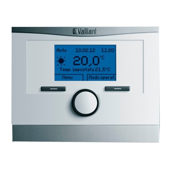
Storing documents ▶ Store these instructions and all other applicable docu- ments for further use. Validity of the instructions These instructions apply only to: Product article number VRT 350 0020124475 Display Right selector button Wall base Rotary knob Diagnosis socket... -
Page 7: Control Function
If a VR 66 Control Centre is connected, you can control two If the control is installed in a living room, you can operate the independent heating circuits with just one VRT 350 control- heating installation and domestic hot water generation from a ler;... -
Page 8: Data Plate
Data plate Operation The data plate is located inside the control and is not access- Operating structure ible from the outside. 4.1.1 Adjustment and display levels Serial number The product has two adjustment and display levels. The 10-digit article number can be found in the serial num- The end user level contains information and setting options ber. - Page 9 – 4.1.3 Basic display do not operate the control for more than 5 minutes. 4.1.3.1 Symbols for the Auto operating mode Symbol Meaning Day mode: Within a set time period Auto 01.07.11 15:34 19,5 °C Night mode: Outside a set time period Desired temperature 20,0°C 4.1.3.2 Soft key function Menu...
-
Page 10: Operating Concept
4.1.3.4 Operating mode Through the selection levels, you navigate to the setting level in which you wish to read or change settings. If you press the right-hand selection button, Operating mode, you access the settings directly from the basic display 4.1.5 Setting level under Operating mode. - Page 11 4.2.1.2 Changing the Desired day temperature If you do not operate the control during a period of more than 5 minutes, the basic display appears again. permanently Turn the rotary knob to set the desired temperature. 4.2.1 Example: Operation in the basic display Press the right-hand selection button, OK.
- Page 12 Basic settings Menu Language Information Date/time Desired temperatures Display Time programmes Back Select Back Select Turn the rotary knob until the Default settings list entry Turn the rotary knob until the Date/Time list entry is is highlighted. highlighted. Basic settings Menu Language Language...
- Page 13 Date/time Date/time Date 14.03.11 Date 13.03.11 Time Time Daylight saving time Daylight saving time Back Change Cancel Press the right-hand selection button, Change. Press the right-hand selection button, OK, to confirm ◁ the change. The highlighted value starts to flash; you can now ◁...
-
Page 14: Operating And Display Functions
Operating and display functions 5.1.2 Reading the list of status messages Menu → Information → System status → Status The path details given at the start of each function descrip- – If no service is required and no faults have occurred, the tion indicate how you reach this function in the menu struc- value OK is shown next to Status. -
Page 15: Settings
Settings 5.2.1.2 Domestic hot water generation 5.2.1 Setting desired temperatures Danger! Risk of scalding caused by hot water. This function is used to set the desired temperatures for HEATING 1 and hot water generation. There is a risk of scalding at the domestic hot water draw-off points if the temperatures 5.2.1.1 Heating circuit are greater than 60 °C. - Page 16 5.2.2 Setting time programmes 5.2.2.2 Setting time periods for days and blocks 5.2.2.1 Showing time periods for one day For each day and block, you can set up to three time periods. The time periods set for a day have priority over the time periods set for a block.
- Page 17 5.2.2.4 Displaying and changing different times in The set times for the block marked with !! can be viewed and changed if you press the right-hand selection button OK in the block the display. Monday - Sunday 5.2.2.5 For the heating circuit Period 1: !! : !! - !! : !! Menu →...
- Page 18 5.2.4 Select language For domestic hot water generation, the time programmes are only effective in Automatic mode. Note In each time period set, the desired DHW circuit temperat- During installation, the competent person sets the ure applies. At the end of a time period, the control switches desired language.
- Page 19 – 5.2.4.1 Setting your language You can use this function to set whether the controller automatically changes over to daylight saving time, or Press the left-hand selection button repeatedly until the whether you want to do this manually. basic display appears. –...
- Page 20 One room thermometer constantly shows a temperature that Caution. is one degree higher than the current room temperature on Risk of a malfunction. the controller display. With the Room temperature func- tion, you can offset the temperature difference in the con- The Everything function restores all settings troller display by setting a correction value of +1 K (1 K cor- to the factory settings, including those set by...
-
Page 21: Operating Modes
Operating modes 5.3.1.3 Comfort mode Operating mode → Comfort mode Use the right-hand selector button, Operating mode to set the mode directly. – The Comfort mode operating mode brings the heating The path details given at the start of each mode description circuit to the set desired day temperature, without taking indicate how you reach this mode in the menu structure. -
Page 22: Special Operating Modes
5.3.2.1 Automatic mode 5.3.2.3 Comfort mode The automatic mode controls the hot water generation in ac- The comfort mode controls the hot water generation in ac- cordance with the set desired temperature for Hot water cir- cordance with the set desired temperature for DHW circuit cuit and the set time periods. -
Page 23: Messages
tion brings the room temperature to the desired Set-back or until you cancel the advanced function early. The heat- ing system will then return to the pre-set mode. temperature. Hot water generation is switched off and frost protection is 5.4.2 Party activated. - Page 24 ▶ If the control displays a fault message, Service heat generator 1 inform a competent person. 22,5 °C Desired temperature 20,0°C Heat generator 1 fault Menu Op. mode The following service messages may appear: – Back Service heat generator 1 –...
-
Page 25: Troubleshooting
Guarantee and customer service Guarantee Care and maintenance We only grant a Vaillant manufacturers warranty if a suitably Caring for the product qualified engineer has installed the system in accordance with Vaillant instructions. The system owner will be granted ▶... -
Page 26: Appendix
Appendix Overview of operating levels Setting level Values Unit Increment, select Default setting Setting Min. Max. Information → System status → (Information → System status →) System or System status (System) Status (Status) Current value Water pressure (Water pressure) Current value Domestic hot water (Domestic hot Current value Charging, Not charg. - Page 27 Setting level Values Unit Increment, select Default setting Setting Min. Max. Information → Serial number → (Information → Serial number →) Unit number Permanent value Desired temperatures → HEATING 1 → (Desired temperatures → HEATING CIRCUIT 1 →) ℃ Day (Day) Set-back (Set-back) Desired temperatures →...
- Page 28 Setting level Values Unit Increment, select Default setting Setting Min. Max. Period 1: Start – End (time period 00:00 24:00 hr:min 10 min Monday - Fri- 1: Start – End) day: 06:00- 22:00 Period 2: Start – End (time period 2: Start –...
- Page 29 Setting level Values Unit Increment, select Default setting Setting Min. Max. Period 1: Start – End (time period 00:00 24:00 hr:min 10 min Monday - Fri- 1: Start – End) day: 05:30- 22:00 Period 2: Start – End (time period 2: Start –...
- Page 30 Setting level Values Unit Increment, select Default setting Setting Min. Max. Time (Time) 00:00 24:00 hr:min 10 min 00:00 Daylight saving time (Daylight Auto, Off Off (Off) saving time) (Auto, Off) Basic settings → Display → (Default settings → Display →) Display contrast (Display con- trast) Basic settings →...
-
Page 31: B Technical Data
Setting level Values Unit Increment, select Default setting Setting Min. Max. Enter code (Enter code) Technical data Control Designation Value 24 V Operating voltage Umax Power consumption < 50 mA Supply line cross-section 0.75 to 1.5 mm² IP rating IP 20 Protection class Maximum permissible environ- 60 ℃... -
Page 32: Index
Index Desired temperatures Heating circuit ..............15 set ...................15 Setting................15 Advanced functions Cylinder boost..............22 Display System status ..............14 Party ................23 Article number ................8 Time programmes............17 Automatic mode ..............21 Display level ................8 Display, contact details for the competent person ....14 Basic display ................9 Documents ................6 Domestic hot water generation.........7, 15 CE marking................8... - Page 33 Serial number .................8 Offset room temperature Service message..............23 Setting................19 Set-back mode ..............21 Operating and display functions ...........14 Setting Operating concept ..............10 Offset room temperature ..........19 Operating example, setting the date ........11 Setting level................10 Operating level ...............8 Setting the date ..............19 Operating mode..............
- Page 36 Supplier Vaillant Ltd. Nottingham Road Belper Derbyshire DE56 1JT Telephone 0330 100 3143 info@vaillant.co.uk www.vaillant.co.uk 0020135485_02 Publisher/manufacturer Vaillant GmbH Berghauser Str. 40 D-42859 Remscheid Tel. +49 2191 18 0 Fax +49 2191 18 2810 info@vaillant.de www.vaillant.de © These instructions, or parts thereof, are protected by copyright and may be reproduced or distributed only with the manufacturer's written consent.
Need help?
Do you have a question about the VRT 350 and is the answer not in the manual?
Questions and answers