Renishaw NC4 Installation Manual
Non-contact tool setting separate system
Hide thumbs
Also See for NC4:
- Installation and maintenance manual (112 pages) ,
- Cleaning instructions manual (16 pages) ,
- Quick start manual (16 pages)

Related Manuals for Renishaw NC4


Summary of Contents for Renishaw NC4
- Page 1 Installation guide NC4 non-contact tool setting separate system www.renishaw.com/nc4 #renishaw...
- Page 2 Compliance information for this product is available by scanning the QR code or visiting www.renishaw.com/mtpdoc...
-
Page 3: Table Of Contents
NC4 non-contact tool setting separate system software notices . . . . . . . . . . . . . . . . - Page 4 NC4 separates installation pack, supplied with: . . . . . . . . . . . . . . . . . . . . . . . . . . . . . . . . . . . . . . . . . . . . .6-2 NC4 non-contact tool setting system...
-
Page 5: Before You Begin
Renishaw office. Renishaw warrants its equipment and software for a limited period (as set out in the Standard Terms and Conditions), provided that they are installed and used exactly as defined in associated Renishaw documentation. -
Page 6: Patents
Patents Features of the NC4 non-contact tool setting separate system and features of similar Renishaw products, are the subject of one or more of the following patents and/or patent applications: CN 100394139 JP 4520240 EP 1502699 US 7312433 NC4 non-contact tool setting separate system software... -
Page 7: Safety
Safety Information to the user The NC4 set-up tool (Renishaw part no. A-4114-8000, sold separately) is supplied with non-rechargeable lithium metal batteries. Refer to the battery manufacturer’s literature for specific battery operating, safety and disposal guidelines . • Do not attempt to recharge the batteries . -
Page 8: Information To The Machine Supplier / Installer
Renishaw product literature, and to ensure that adequate guards and safety interlocks are provided . If the NC4 unit fails, the output signal may falsely indicate beam not blocked . Do not rely on signals from the NC4 unit to halt the movement of the machine . -
Page 9: Warnings
A warning label and explanatory label are permanently fixed to each side of the transmitter (Tx) housing (see page 1-6, “Laser safety and warning labels”, for further information). An adhesive warning label is also provided . Renishaw advise attaching this label to the outside of the machine tool, in a visible location . www.renishaw.com/nc4... -
Page 10: Laser Safety And Warning Labels
Caution symbol (see “CAUTION symbol” below, for further information) Laser aperture / MicroHole™ Access panel identification markings, denoting system range (for more information, see the NC4 non-contact tool setting system accessories data sheet (Renishaw part no. H-2000-2223)). CAUTION – LASER SAFETY CAUTION SYMBOL... -
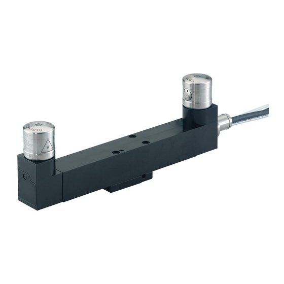
Page 11: Nc4 Basics
NC4 basics Introduction This guide describes how to install, configure, maintain and service the Renishaw NC4 non-contact tool setting system . The NC4 is a laser-based non-contact tool setting system that provides high-speed/high-precision measurement of cutting tools on a machining centre under normal operating conditions . -
Page 12: Guidelines For Best Practice
Mount the NC4 unit in a position that limits the risk of it being subjected to impact when operating the machine . • Mount the NC4 unit in a position where it will not be affected by a build-up of swarf . Do not allow excessive waste material to build up on or around the NC4 unit . •... -
Page 13: Nc4 Specification
Other configurations are available on request. Barrier air Air supply to the NC4 must conform to BS ISO 8573-1 Class 1 .4 .2 . 6 .0 bar pneumatic supply (87.02 psi) maximum. Air pipe: Ø3.0 mm (0.12 in) × 5.0 m (16.40 ft). -
Page 14: Nc4 Specification (Continued)
NC4 specification (continued) Mounting Mounting achieved via a 3-plate or single plate adjuster pack (sold separately); see the NC4 non-contact tool setting accessories data sheet (Renishaw part number H-2000-2223). Environment IP rating IPX6 and IPX8, BS EN 60529:1992+A2:2013 Storage –25 °C to +70 °C (–13 °F to +158 °F) -
Page 15: Dimensions Of Nc4 Units
Dimensions of NC4 units Ø30 (Ø1.18) 24 (0.95) A/F Ø26 (Ø1.02) 7.5 (0.29) Mounting holes (×2) M3 × 0.5 P × 8 (0.32) deep. Dowel holes (×2) Ø2 × 8 (0.32) deep. Pneumatic push-fit connector Ø3 (Ø.12) plastic pipe . - Page 16 This page is intentionally left blank . NC4 non-contact tool setting system: System installation...
-
Page 17: System Installation
Switch on electrical power to the NCi-6 interface unit (see page 3-8, “Supplying electrical power to the NCi-6 interface unit”, for further information). Switch on the barrier air supply to the NC4 unit and set the air pressure (see page 3-9, “Setting the NC4 barrier air pressure”, for further information). -
Page 18: Air Supply Information
Air supply information The barrier air supply to the NC4 unit must conform to BS ISO 8573-1 air quality of Class 1 .4 .2 and be moisture-free. If the air quality cannot be guaranteed, an air preparation pack is available from Renishaw;... -
Page 19: Installing The Air Preparation Pack
Secure the air preparation pack, vertically upright, to a suitable surface using the mounting brackets . This must be within 25 m (82.02 ft) of the NC4 unit. NOTE: The membrane dryer features a small vent from which humid air is purged . Air can be heard venting from this port during operation . -
Page 20: Installing The Nc4 System
. Connect the Ø3 mm barrier air pipe to the air inlet of the NC4 unit . Fit the Ø3 mm to Ø4 mm straight adaptor pneumatic fitting and blanking cap to the free end of the Ø3 mm air pipe. - Page 21 Screw covers (to keep the assembly together during transit) Secure the NC4 unit to mounting plate A with the two M3 holding screws . Feed the electrical cable and air pipe through mounting plates B and C . 3-plate adjuster...
- Page 22 16 . Remove the straight adaptors and blanking caps from the end of the air pipes . 17 . Before connecting any pipe to the NC4 unit, use the air regulator to purge the pipe and remove any debris .
-
Page 23: Installing The Nci-6 Interface Unit
. The NCi-6 interface unit processes signals from the NC4 unit and converts them into a voltage-free solid state relay (SSR) output. This is transmitted to the CNC machine controller. -
Page 24: Nc4 System Wiring Details
If electrical power to the NCi-6 interface unit is lost and subsequently restored when the NC4 system is in a normal operating mode, the NC4 system powers down and then powers up again without loss of the original gain settings . -
Page 25: Setting The Nc4 Barrier Air Pressure
(7.25 psi). Check that the profile of the laser beam is circular. NOTES: If the air supply pressure varies while the machine is operating, the air pressure to the NC4 unit may need to be increased to allow for this pressure fluctuation. -
Page 26: Macro Programming Software
Readme file on the software media. Software routines for tool setting using various machine controllers and available software packages are described in the Probe software for machine tools – programs and features data sheet (Renishaw part no. H-2000-2298, available at www.renishaw.com). -
Page 27: Head Alignment Of The Nc4 Unit
. Do this with the NCi-6 interface unit in set-up mode . Either a voltmeter or an NC4 set-up tool can be used to provide an indication of the signal strength received at the receiver head . - Page 28 Load a tool into the spindle of the machine. A solid, flat-bottomed tool is preferred. Attach a target marker to the tool, as shown in the figure below. Target position 2 Target position 1 3-12 NC4 non-contact tool setting system: System installation...
- Page 29 20 . If the beam is blocked when the switch is set to “Off”, the system will be unable to set itself correctly . If this occurs remove the obstruction then set switch SW1-2 (NC set-up) to “On” then back to “Off”. www.renishaw.com/nc4 3-13...
-
Page 30: Aligning The Nc4 Unit To The Machine Axes
Aligning the NC4 unit to the machine axes WARNING: Before aligning and setting up an NC4 unit, ensure that the machine is safe to work on . This procedure involves moving the NC4 unit so that the laser beam is parallel/perpendicular to the machine’s axes. -
Page 31: Alignment Tolerances
NOTE: For best measurement performance, Renishaw recommends aligning NC4 units using a ball-nosed cylinder-type calibration tool. A mobile app (NC4 app) is available for step-by-step instructions on NC4 unit alignment (for more information, see page 3-10, “Machine tool apps”). - Page 32 This page is intentionally left blank . 3-16 NC4 non-contact tool setting system: System installation...
-
Page 33: Maintenance
Maintenance Introduction The NC4 unit requires minimal maintenance as it has been designed to operate as a permanent fixture on all sizes of vertical and horizontal machining centres, multi-tasking machines and gantry machining centres where it is subject to an environment of hot metal chips and coolant . -
Page 34: Removing And Refitting The Air Preparation Filter Elements
Fit a new O-ring into the recess in the filter bowl. Refit the filter bowl and screw hand-tight. Switch on the air supply and set the pressure as described in “Setting the NC4 barrier air pressure” on page 3-9 . -
Page 35: Removal And Replacement Of Membrane Dryer Module
. Replace membrane and dew point indicator . NOTE: Items shown within dotted boxes (B) and (C) are included in the membrane dryer service pack obtainable from Renishaw; see the NC4 non-contact tool setting accessories data sheet (Renishaw part no. H-2000-2223). www.renishaw.com/nc4... - Page 36 NC4 non-contact tool setting system: Maintenance...
-
Page 37: Cleaning The Optics
Cleaning the NC4 unit If the air to the NC4 unit becomes contaminated, the transmitter and receiver heads may require cleaning . Contamination will cause the system to stay in a triggered state . If contamination is suspected, identify the cause and rectify the problem (for more information, see “Fault-finding”... -
Page 38: To Clean The Optics
CAUTION – LASER SAFETY The access panel of an NC4 transmitter head is removed to allow access to the optics . Before removing the panel, switch off electrical power to the NC4 unit to avoid exposure to the laser beam . -
Page 39: After Cleaning The Nc4 Unit
12 . Remove the cleaning tool. Refit the access panel using the pin spanner. Tighten to 2.0 Nm (1.48 lbf.ft). 13 . Repeat the cleaning procedure for the other NC4 head (ensure both Tx and Rx heads are clean). After cleaning the NC4 unit Reconnect and switch on electrical power to the NCi-6 interface unit (for more information, see “Supplying electrical power to the NCi-6 interface unit”... -
Page 40: Using A Voltmeter
Using a voltmeter A standard voltmeter, that is within calibration, may be used for setting up and aligning the NC4 transmitter and receiver heads . Position the voltmeter next to the receiver head . Connect a wire between terminal CN1-1 on the NCi-6 interface unit and one of the voltmeter probes . -
Page 41: Nc4 Set-Up Tool
The NC4 set-up tool (Renishaw part no. A-4114-8000, sold separately) is a battery-operated device that is used to provide a visual indication of the signal strength at the NC4 receiver head . The signal strength is shown on a numerical display . The higher the number, the greater the signal received at the receiver head . -
Page 42: Using The Set-Up Tool
– that is, when the NC set-up switch (SW1-2) is set to ‘On’. Check that the NC4 receiver head is clean and free of swarf . Push the set-up tool onto the top of the receiver head and rotate it so that the display is facing you . -
Page 43: Replacing The Set-Up Tool Battery
Typically, this specification can be provided by a cell containing Lithium-thionyl chloride (3.6 V). This is recommended for maximum battery life. A Lithium-thionyl chloride (3.6 V) battery will last the equivalent of 700 hours’ continuous operation . Battery manufacturer Part number Saft LS 14250 Tadiran SL-750 Xeno XL-050F www.renishaw.com/nc4 4-11... -
Page 44: Status Led Function
Status LED function The status LEDs on the NC4 transmitter and receiver heads indicate to the user the status of the unit . The LEDs mimic each other . Status LED (on transmitter and receiver heads) Colours shown by the LEDs vary depending upon the mode of operation of the NCi-6 interface unit . - Page 45 No power to the unit . The status LEDs can be used for diagnostic purposes, as the NC4 system constantly checks for signal and indicates the state of the system by the colours of the LEDs . If the laser beam is clear and the LEDs are either amber or flashing green/amber, this indicates that servicing is required.
- Page 46 This page is intentionally left blank . 4-14 NC4 non-contact tool setting system: Fault-finding...
-
Page 47: Fault-Finding
Damaged cable . Replace the cable . No laser beam is The PassiveSeal is protecting Check that the air supply to the NC4 system is exiting the transmitter switched on (for more information, see page the device . (Tx and Rx status 3-9, “Setting the NC4 barrier air pressure”). - Page 48 Symptom Cause Action Poor repeatability/ Poor tool change repeatability . Check repeatability of the NC4 without spurious readings performing a tool change . (continued). Poorly regulated power Ensure that the power supply is correctly supply . regulated . Coolant drips or mist .
- Page 49 . The unit is untriggered . This is not a fault . NC4 status LED is No air supply to the NC4 . Check the air supply . red. Damaged air pipes .
- Page 50 . Coolant build up/deposits on Clean the top of the NC4 outer cover to ensure NC4 cover . good electrical contact to the set-up tool . Battery fitted incorrectly.
-
Page 51: Parts List
Item Part number Description NC4 0 .3 m to 0 .5 m A-4114-5005 NC4 Tx unit (access panel with 20 identification marking) and separation unit pack NC4 Rx unit (access panel with 40 identification marking). NC4 0 .5 m to 0 .8 m... -
Page 52: Nc4 Separates Installation Pack, Supplied With
Item Part number Description NC4 0 .3 m to 0 .5 m A-4114-5055 NC4 0 .3 m to 0 .5 m separation pack, including NC4 Tx unit separation pack (access panel with 20 identification marking) and NC4 Rx unit (access panel with 40 identification marking). - Page 53 TARGET TO AID ALIGNMENT TARGET TO AID ALIGNMENT TARGET TO AID ALIGNMENT TARGET TO AID ALIGNMENT...
- Page 54 © 2017–2023 Renishaw plc . All rights reserved . This document may not be copied or reproduced in whole or in part, or transferred to any other media or language by any means, without the prior written permission of Renishaw .
Need help?
Do you have a question about the NC4 and is the answer not in the manual?
Questions and answers