Renishaw RTS Installation Manual
Radio tool setter
Hide thumbs
Also See for RTS:
- Installation manual (48 pages) ,
- Quick start manual (46 pages) ,
- Quick start manual (36 pages)
Table of Contents
Advertisement
Quick Links
Advertisement
Table of Contents

Related Manuals for Renishaw RTS


Summary of Contents for Renishaw RTS
- Page 1 Installation guide H-6589-8520-01-A RTS (QE) radio tool setter...
- Page 2 This document may not be copied or reproduced in whole or in part, or transferred to any other media or language, by any means, without the prior written permission of Renishaw plc. Renishaw plc. Registered in England and Wales. Company no: 1106260. Registered office: New Mills, Wotton-under-Edge, Gloucestershire, GL12 8JR, UK.
-
Page 3: Table Of Contents
RTS (model RTSQE) software licensing agreement ....... . . 1.3... - Page 4 Installing the RTS with an RMI-Q or RMI-QE ....... . .
- Page 5 Maintenance ..............5.1 Maintenance .
- Page 6 This page is intentionally left blank.
-
Page 7: Before You Begin
Renishaw office. Renishaw warrants its equipment and software for a limited period (as set out in the Standard Terms and Conditions), provided that they are installed and used exactly as defined in associated Renishaw documentation. -
Page 8: Cnc Machines
Care of the probe Keep system components clean and treat the probe as a precision tool. Patents Features of the RTS, and other similar Renishaw products, are the subject of one or more of the following patents and/or patent applications: CN 100466003... -
Page 9: Rts (Model Rtsqe) Software Notices
RTS (model RTSQE) software notices This RTS product includes embedded software (firmware) to which the following notices apply: US government notice NOTICE TO UNITED STATES GOVERNMENT CONTRACT AND PRIME CONTRACT CUSTOMERS This software is commercial computer software that has been developed by Renishaw exclusively at private expense. -
Page 10: Intended Use
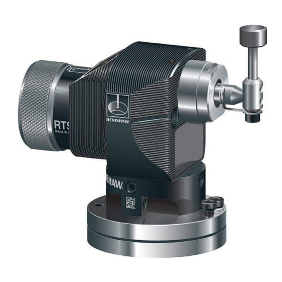
Intended use The RTS is a radio tool setting probe that enables automated broken tool detection and rapid measurement of the tool length and diameter of a wide range of tools on machining centres of all sizes. Safety Information to the user This product is supplied with non-rechargeable batteries that do not contain lithium. - Page 11 Information to the equipment installer All Renishaw equipment is designed to comply with the relevant UK, EU and FCC regulatory requirements. It is the responsibility of the equipment installer to ensure that the following guidelines are adhered to, in order for the product to function in accordance with these regulations: •...
- Page 12 This page is intentionally left blank.
-
Page 13: Rts Basics
The RTS is part of the latest generation of radio transmission probes. It has been designed to comply with worldwide standards and operates in the 2.4 GHz band. It delivers interference-free transmission through the use of hybrid FHSS (frequency-hopping spread spectrum) technology, which allows multiple systems to operate in the same machine shop without risk of interference. -
Page 14: Getting Started
H-6551-8520). It is necessary that the RTS is partnered to either an RMI-Q or RMI-QE. Prior to partnering for the first time, the RTS is pre-set to operate in RMI-QE mode. The LED check will display double flashes of red, green, blue. -
Page 15: Probe Configuration
China. Opti-Logic™ Opti-Logic is the process of transmitting and receiving data from the app to a Renishaw machine tool probe using pulses of light; for more information, see page 4.1, “Configuring the probe using the Probe Setup app”. -
Page 16: Probe Modes
Standby mode – Probe is waiting for a switch-on signal. NOTE: The RTS will enter “hibernation mode” should the system interface be powered off or out of range for a period of 30 seconds. “Hibernation mode” is only applicable to “radio on mode” when used with a RMI-Q. -
Page 17: Hibernation Mode
Display of “Hibernation mode” indicates that the RTS is in RMI-Q mode. NOTES: Prior to partnering for the first time, the RTS is pre-set to operate in RMI-QE mode. The LED check will display double flashes of red, green, blue. -
Page 18: Switch-On Time
Switch-on time (configured by RMI-Q or RMI-QE) When the RTS is used with an RMI-Q or RMI-QE, the turn-on time can be configured (in the interface) to either “fast” or “standard”. For best battery life, select ‘standard’ turn-on time. A timer automatically switches the probe off 90 minutes after the last probe status change if not turned off by an M-code. -
Page 19: Recommended Rotating Tool Feedrates
Recommended rotating tool feedrates Cutters should be rotated in the opposite direction to the cutting direction. Renishaw tool setting software calculates speeds and feeds automatically using the following information. First touch – machine spindle r/min r/min for the first move against the probe stylus: Diameters below 24 mm: 800 r/min is used. -
Page 20: Rts Dimensions
× 13 (0.51) deep MIN Typical bolt length 5.95 (0.23) 30 (1.18) equi-spaced on Ø54 (2.125) PCD at 45° to RTS axis supplied by user Machining details for dowel pins 2 × Ø6 mm dowel pin holes M/C bed holes for dowel pins Ø54 (2.126) - Page 21 RTS dimensions (continued) Square stylus Disc stylus 19.05 mm × 19.05 mm (0.75 in × 0.75 in) Ø12.7 mm × 8 mm (Ø0.5 in × 0.31 in) Tungsten carbide 75 Rockwell C Ceramic 75 Rockwell C 19.05 (0.75) Cranked horizontal stylus adaptor kit...
-
Page 22: Rts Specification
RTS specification Principal application Tool measuring and broken tool detection on vertical and horizontal machining centres and gantry machining centres. Overall dimensions Length with disc stylus 116.40 mm (4.58 in) Length with square stylus 119.58 mm (4.71 in) 2.10 Width 62.50 mm (2.46 in) -
Page 23: Typical Battery Life
2160 hours 2160 hours NOTES: Battery life figures quoted in the above table are applicable to the RTS (model RTSQE) when used with a RMI-QE interface/receiver. Using an RMI-Q interface/receiver will result in a reduction from the figures quoted. 1% usage = 14 minutes/day. - Page 24 2.12 This page is intentionally left blank.
-
Page 25: System Installation
Wipe clean as often as is necessary to maintain unrestricted transmission. When in operation, do not touch either the RMI-Q or RMI-QE cover or the RTS glass window with your hand as this can also affect transmission performance. -
Page 26: Positioning The Rts And Rmi-Q Or Rmi-Qe
RTS goes from “hibernation mode” to “stand-by mode”, ready for an M-code. If the RTS goes out of range (for example, if the RTS is fitted to a pallet which is removed from the machine), the system will automatically re-synchronise within 30 seconds once the RTS is back in range. Allowance must be made within the machine controller program for this. - Page 27 Performance envelope when using the RTS with the RMI-Q or RMI-QE RMI-Q 75° 15 (49) 60° RMI-QE 90° 105° 75° 45° 60° 120° 10 (33) 135° 45° 30° 150° 30° 5 (16) 15° 165° 15° 15 (49) 10 (33) 5 (16) 0°...
-
Page 28: Preparing The Rts For Use
Preparing the RTS for use Fitting the stylus, break stem and captive link Stylus weak link break stem A stylus weak link break stem is incorporated in the stylus mounting. This protects the probe mechanism from damage in the event of excessive stylus overtravel or a collision. -
Page 29: Installing The Batteries
Installing the batteries NOTES: Ensure the product is clean and dry before inserting batteries. Do not allow coolant or debris to enter the battery compartment. When inserting batteries, check that the battery polarity is correct. After inserting the batteries, the LED will display the current probe settings (for more information, see page 4.2,“Reviewing the probe settings”). -
Page 30: Mounting The Probe On A Machine Table
Separate the base from the body by slackening four screws 1 and two screws 2 using a 2.5 mm A/F hexagon key. Fit the cap head bolt and T nut (not supplied by Renishaw) and tighten to secure the base to the machine table. -
Page 31: Stylus Level Setting
Stylus level setting The top surface of the stylus must be set level, front to back and side to side. Side-to-side level adjustment Side-to-side level adjustment is obtained by alternately adjusting grub screws 1, which causes the probe module to rotate and changes the stylus level setting. When a level stylus surface is obtained, tighten screws 1. -
Page 32: Stylus Level Setting (Continued)
Stylus level setting (continued) Front-to-back level adjustment To raise the front, slacken locking screw 2 and adjust height adjusting screw 3 until the stylus is level, then fully tighten locking screw 2. To lower the front, slacken height adjusting screw 3 and adjust locking screw 2 until the stylus is level, then fully tighten locking screw 3. -
Page 33: Square Stylus Setting Only
Square stylus setting only Square stylus rotational adjustment allows the stylus to be aligned with the machine axes. Coarse rotational adjustment Slacken grub screw 1, rotate the stylus by hand to obtain alignment, then fully tighten the grub screw. NOTE: Always hold the support bar in position to counteract twisting forces and avoid over-stressing the stylus break stem. - Page 34 Square stylus setting only (continued) Fine rotational adjustment Slacken the four body locking screws 2. 3.10...
- Page 35 Square stylus setting only (continued) Fine rotational adjustment (continued) Opposing grub screws 3 are tightened against a locating pin fixed to the base. By alternately slackening and re-tightening these grub screws, fine rotational adjustment of the stylus is achieved. Then tighten the grub screws. 3.11 ±...
- Page 36 Square stylus setting only (continued) Fine rotational adjustment (continued) Tighten the four body locking screws 2. 3.12 2.5 mm AF 0.7 Nm – 0.9 Nm (0.52 lbf.ft – 0.66 lbf.ft) × 4...
-
Page 37: Calibrating The Rts
When the probe has been correctly set up on the machine, it is time to calibrate the probe. Calibration cycles are available from Renishaw for this task. The purpose is to establish the probe stylus measuring face trigger point values under normal measuring conditions. - Page 38 3.14 This page is intentionally left blank.
-
Page 39: Probe Configuration
Renishaw machine tool probing system. Using Opti-Logic™ Opti-Logic™ is the process of transmitting and receiving data from the app to a Renishaw machine tool probe using pulses of light. The app will ask for the probe version to be entered. The probe version is displayed at the back of the battery compartment which is visible when the battery cassette is removed. -
Page 40: Reviewing The Probe Settings
Reviewing the probe settings Key to the symbols LED short flash LED long flash > 5 s LED check RMI-Q RMI-QE Trigger filter Level 1 Level 2 Hibernation mode (RMI-Q only) 30 s Battery status Battery low Battery good Probe in standby mode (after 5 seconds) -
Page 41: Probe Partnering Function
RMI-Q or RMI-QE must be turned on. If an RMI-Q is turned on, the RTS will continue to display the sequence of light blue flashes. If an RMI-QE is turned on, the RTS display sequence will now incorporate a long yellow flash. -
Page 42: With Rmi-Q Switched On
Whilst the “Battery status” is being displayed, deflect and release the stylus to enter “Partnering mode”. Probe status will flash red to acknowledge this. NOTE: Wait until the first battery status flash has occurred before deflecting the stylus, and then release the stylus when the red flash is observed. -
Page 43: Rts - Rmi-Q Partnership
RMI-Q can be achieved by using ReniKey; a Renishaw machine macro cycle which does not require the RMI-Q to be power cycled. Partnering is required during initial system set-up. Further partnering will be required if either the RTS or RMI-Q is changed. -
Page 44: Rts - Rmi-Qe Partnership
Partnering will not be lost by reconfiguring the probe settings or changing the batteries. Partnering can take place anywhere within the operating envelope. An RTS that is partnered with the RMI-QE but then used with another system will need to be repartnered before being used again with the RMI-QE. - Page 45 Displayed for 5 seconds The probe is now in standby and the system is ready for use. > 20 s NOTE: Refer to the RMI-QE radio machine interface installation guide (Renishaw part no. H-6551-8520) when partnering up to four radio probes.
-
Page 46: Changing The Probe Settings When Partnering To An Rmi-Q
Changing the probe settings when partnering to an RMI-Q Probe settings can be changed using Trigger Logic. Insert the batteries or, if they have already been installed, remove them for 5 seconds and then refit them. Following the LED check, immediately deflect the stylus and hold it deflected until eight red flashes have been observed (if the battery power is low, each red flash will be followed by a blue flash). - Page 47 NOTE: To partner an RTS with an RMI-Q see page 4.5, “RTS – RMI-Q partnership”, for further information. Once partnering has been successful, the RTS will display “Partnering successful” and go into standby after 20 seconds.
-
Page 48: Changing The Probe Settings When Partnering To A Rmi-Qe
Battery status Battery good Battery low Trigger filter Level 1 Level 2 New settings complete, probe in standby NOTE: To partner an RTS with an RMI-QE, see page 4.3, “Probe partnering function”, for further information on how to reach “Partnering mode”. -
Page 49: Master Reset Function
Master reset function RTS features a master reset function to assist users who have mistakenly changed the probe settings into an unintended state. The application of the master reset function will clear all current probe settings and return the probe to default settings. - Page 50 4.12 Battery status Battery good Battery low Trigger filter Level 1 Level 2 Release the stylus. Deflect the stylus for 20 seconds until the status LEDs start to flash yellow eight times. Whilst the status LEDs are flashing yellow to confirm that a master reset is required, release the stylus and then hold the stylus deflected again until the eight yellow flash...
- Page 51 Probe is now back in the Trigger 4.13 Trigger filter Logic menu and will display “Trigger filter”. Configure probe settings as required using Trigger Logic NOTE: RTS will continue to be partnered with either the RMI-Q or RMI-QE following the activation of the master reset function.
-
Page 52: Operating Mode
Operating mode Opti-logic 4.14 Multicoloured probe status LED Probe status LEDs LED colour Probe status Graphic hint Flashing green Probe seated in operating mode Flashing red Probe triggered in operating mode Flashing green and blue Probe seated in operating mode – low battery Flashing red and blue Probe triggered in operating mode –... -
Page 53: Maintenance
Wipe the window of the probe with a clean cloth to remove machining residue. This should be done on a regular basis to maintain optimum transmission. CAUTION: The RTS has a glass window. Handle with care if broken to avoid injury. -
Page 54: Changing The Batteries
Changing the batteries CAUTIONS: Do not leave dead batteries in the probe. When changing batteries, do not allow coolant or debris to enter the battery compartment. Ensure the product is clean and dry before inserting batteries. When changing batteries, check that the battery polarity is correct. Take care to avoid damaging the battery compartment gasket. -
Page 55: Battery Types
Tadiran: SL-560/S, Xeno: XL-060F TL-4903/S ¬¬ AA battery types are also designated as LR6 or MN1500. NOTE: Lithium-thionyl chloride batteries are available from other manufacturers. However, these are untested by Renishaw so correct operation of the probe cannot be guaranteed. -
Page 56: Routine Maintenance
Approximately once a month, inspect the probe inner diaphragm seal (see page 5.5, “Inspecting the inner diaphragm seal”, for further information). If it is pierced or damaged contact Renishaw. The service interval may be extended or reduced depending on experience. -
Page 57: Inspecting The Inner Diaphragm Seal
Inspecting the inner diaphragm seal Spanner 24 mm or 15/16 in 2.7 Nm – 3.3 Nm (1.99 lbf.ft – 2.43 lbf.ft) Inner diaphragm seal Spring Metal eyelid seal Spanner 5 mm A/F 2.4 Nm – 2.8 Nm (1.77 lbf.ft – 2.07 lbf.ft) Front cover Stylus and break stem assembly... - Page 58 This page is intentionally left blank.
-
Page 59: Fault-Finding
Unsuitable batteries. Fit suitable batteries. Batteries inserted incorrectly. Check battery insertion/polarity. Radio link failure / RTS out of range. Check position of RMI-Q or RMI-QE; for more information, see page 3.2, “Positioning the RTS and RMI-Q or RMI-QE”. - Page 60 Symptom Cause Action The machine stops Radio link failure / RTS out of Check interface/receiver and unexpectedly during a range. remove obstruction. probing cycle. Check position of RMI-Q or RMI-QE; for more information, see page 3.2, “Positioning the RTS and RMI-Q or RMI-QE”.
- Page 61 Symptom Cause Action Poor probe repeatability Debris on tool. Clean part and stylus. and/or accuracy. Loose probe mounting on Check and tighten as appropriate. machine bed or loose stylus. Excessive machine vibration. Change trigger filter setting. Eliminate vibrations. Environmental or physical Review probing software.
- Page 62 Symptom Cause Action RTS status LEDs do not Radio link failure – RTS out of Check position of RMI-Q or correspond to RMI-Q or RMI-Q or RMI-QE range. RMI-QE; for more information, see RMI-QE status LEDs. page 3.2, “Positioning the RTS and RMI-Q or RMI-QE”.
- Page 63 Symptom Cause Action The probe goes into Probe trigger function is Return to Renishaw. Trigger Logic™ damaged. configuration mode and cannot be reset. Probe was triggered when Do not touch the stylus or stylus batteries were inserted. mounting face during battery...
- Page 64 This page is intentionally left blank.
-
Page 65: Parts List
Parts list Item Part number Description RTS (QE) A-5646-0001 RTS (QE) probe with disc stylus, AA alkaline batteries, tools and support card. Set to trigger filter off. Disc stylus A-2008-0382 Disc stylus (tungsten carbide, 75 Rockwell C) Ø12.7 mm (Ø0.5 in). - Page 66 Part number Description Publications. These can be downloaded from our website at www.renishaw.com. RTS (QE) QSG H-6589-8500 Quick-start guide: for rapid set-up of the RTS (QE) probe. RMI-Q QSG H-5687-8500 Quick-start guide: for rapid set-up of the RMI-Q. RMI-Q IG H-5687-8504 Installation guide: for set-up of the RMI-Q.
- Page 68 Renishaw plc +44 (0)1453 524524 +44 (0)1453 524901 New Mills, Wotton-under-Edge uk@renishaw.com Gloucestershire, GL12 8JR United Kingdom www.renishaw.com For worldwide contact details, visit www.renishaw.com/contact Issued: 04.2022 Part no. H-6589-8520-01-A © 2022 Renishaw plc...
Need help?
Do you have a question about the RTS and is the answer not in the manual?
Questions and answers