Thitronik WiPro III Installation Manual
Ford transit 2006+
Hide thumbs
Also See for WiPro III:
- Operating instructions manual (68 pages) ,
- Installation manual (20 pages) ,
- Installation manual (9 pages)
Advertisement
Quick Links
Disclaimer:
This installation manual is intended for profes-
sional service companies. Appropriate back-
ground knowledge about work on vehicle elec-
trics and electronics is therefore required.
Improper interventions into the vehicle elec-
tronics and their components can under cer-
tain circumstances cause them to no longer
function as intended. This can considerably
endanger the installer (work, e.g., on the airbag
system) and the roadworthiness of the vehicle
and can result not only in property damage, but
also in personal injury.
Therefore, have all work on the vehicle elec-
tronics carried out by a qualified shop.
1
WiPro III Installation Manual
Thitronik GmbH is not liable for damage to
property and/or personal injury resulting from
improper, incorrect or only partially completed
installation work. The installing service compa-
ny is obligated to ensure that its connection
work neither is faulty in itself nor can lead to
faults or dangers on the vehicle.
The instructions in the WiPro installation man-
ual remain applicable. Unused inputs and out-
puts must be isolated.
Should the given vehicle conditions differ from
those described herein, please contact the
manufacturer or our technical support team.
Updated 12/20
Ford Transit
2006+
Advertisement

Related Manuals for Thitronik WiPro III


Summary of Contents for Thitronik WiPro III
- Page 1 WiPro III Installation Manual Ford Transit 2006+ Disclaimer: Thitronik GmbH is not liable for damage to This installation manual is intended for profes- sional service companies. Appropriate back- property and/or personal injury resulting from ground knowledge about work on vehicle elec- improper, incorrect or only partially completed trics and electronics is therefore required.
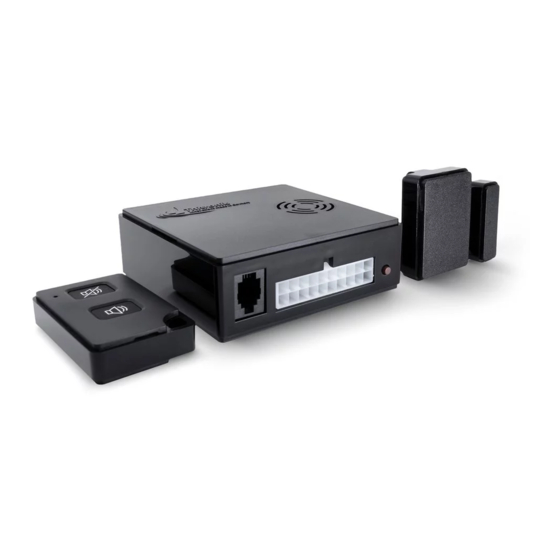
- Page 2 If this is not present, the WiPro is operated via the grey handheld transmitter; the CAN connection continues to serve towards door evaluation. WiPro III Installation Manual – Ford Transit from year of manufacture 2006.
- Page 3 Remove the glove compartment. Release the fuse box. Press the clips outwards and fold down. C2 (brown) C5 (light brown) C6 (white) Localise connectors C2, C5 and C6. WiPro III Installation Manual – Ford Transit from year of manufacture 2006.
- Page 4 Step 4: Make central locking system evaluation connection (connector C2) Use red branch connectors for both connections. Wire colour on Cable colour on Ford WiPro grey/brown → blue violet/orange → blue/black WiPro III Installation Manual – Ford Transit from year of manufacture 2006.
- Page 5 Signals during arming If a series of short beeps is emitted during lock- ing, one of the taught-in magnetic contacts is open. However, the system is armed anyway. WiPro III Installation Manual – Ford Transit from year of manufacture 2006.
- Page 6 Mounting of wireless magnetic contacts 868 to windows, doors, hatches etc. Item no.: 100757, 100758...
- Page 7 1. The orientation of the transmitter housing on the window frame depends on the available space (frame profile, distance to the roller blind or window). Variant lying Variant lying left right Magnet Magnet Transmitter housing Transmitter housing Window frame Window frame 2.
- Page 8 Alternative mounting variants Should upright mounting on the window Variant upright Variant windowpane frame or mounting on the windowpane be necessary, e.g., for space reasons, the transmitter LED must also be aligned pointing away from the magnet. Door or hatch mounting Fixing options Ideally, the transmitter housing is aligned and The wireless magnetic contacts are ideally...
- Page 9 Alignment of circuit board in transmitter housing (as-delivered condition) and positions of components. Top view of Cross section Bottom view of circuit board circuit board Transmitter Transmitter cover Reed Battery switch Transmitter housing Long housing leg Short housing leg Battery Battery Positioning the magnet As long as the magnet is in the yellow area, its...
Need help?
Do you have a question about the WiPro III and is the answer not in the manual?
Questions and answers