Thitronik WiPro III Installation Manual
Hide thumbs
Also See for WiPro III:
- Operating instructions manual (68 pages) ,
- Installation manual (9 pages) ,
- Installation manual (9 pages)

Related Manuals for Thitronik WiPro III


Summary of Contents for Thitronik WiPro III
- Page 1 WiPro III � Installation manual � Hersteller/Manufacturer Thitronik GmbH www.thitronik.de kontakt@thitronik.de Finkenweg 11 – 15 Te l .: +49 (0)4351 76744-0 D 24340 Eckernförde Fax: +49 (0)4351 76744-127 (Germany) Revision 1. 6...
-
Page 2: Table Of Contents
The cab doors on vehicles without a CAN bus are secured by the interior lighting. The system is operated via the original remote key fob or the Thitronik wireless remote control, depending on the vehicle concerned. If a secured opening is opened... -
Page 3: Installation Instructions
For some vehicle types (e.g., Sprinter, T5, T6), the horn will only operate when the ignition is on. The vehicle horn is not triggered by WiPro III in this case. It is recommended to mount a siren in the engine compartment or to use a back-up siren. -
Page 4: Accessories
Protection against “replay attacks” (possible from serial no: 0823-014 or firmware version 5.8) To prevent the control of the WiPro III via the car key, set switch 5 of the DIP switch (A) in sketch 2 on page 6 to position ON. The evaluation of the vehicle doors nevertheless takes place. -
Page 5: Preparing For Installation
Page 11) and make sure that switches 1 – 4 are in the off position. The settings must be made with the circuit de-energised. Make sure that neither the 20-pin plug nor the plug for the Pro-finder are plugged in. Table 1 Other types of vehicles can be found at www.thitronik-automotive.de/en/support/faqs/faq-wipro-iii.html Vehicles from 2006 Years of Switch 1 Switch 2... -
Page 6: Deleting Wireless Components
Installation manual for WiPro III Page 5 1.8 Storing wireless magnetic contacts, wireless remote controls, etc. !! As supplied, no wireless magnetic contacts, etc. are stored !! If the instructions in this chapter are not carried out, the alarm system can- not interpret the signals transmitted by the wireless components, and the wireless components cannot trigger an alarm. -
Page 7: Diagrams
Installation manual for WiPro III Page 6 1.9.1 Diagrams Diagram 1 Diagram 2 Diagram 3 Diagram 4 max. 22 mm < < < > > > Diagram 5 Diagram 6 GSM module connection... -
Page 8: Installing The Wireless Magnetic Contacts
Installation manual for WiPro III Page 7 1.9.2 Installing the wireless magnetic contacts Choose the places where you want to install the wireless magnetic contacts. The transmitters can be installed both on the window and the frame (see diagrams on Page 8). The distance between the transmitter (Diagram 3, Part A, Page 6) and magnet (Diagram 3, Part B, Page 6) can be around 22 mm. -
Page 9: Diagrams
Installation manual for WiPro III Page 8 1.9.5 Diagrams It is possible to mount the transmitter Transmit LED casing in a lying position (on the left or, Transmitter rotated 180°, on the right) or standing cover on the side – depending on the frame Reed sensor and the available space / the distances to the pane. -
Page 10: Installing The Radio Cable Loop (Accessory)
Installation manual for WiPro III Page 9 1.9.6 Installing the radio cable loop (accessory) Choose a suitable place for installation at the back of the vehicle or on one of the sides. You can also obtain further holders as accessories (Item no: 100649) to use the cable loop for other areas of the vehicle. -
Page 11: Can Bus Diagnostics
2 Connecting the central unit to the vehicle systems Connect the WiPro III cable according to the plug assignment diagram on Page 11 and using the connection diagrams on Pages 12 to 15. All connections must be made with the circuits de-energised. - Page 12 Installation manual for WiPro III Page 11 Pin assignment of the 20-pin plug connector...
- Page 13 Installation manual for WiPro III Page 12 Universal connection diagram This connection diagram shows the available connections for WiPro on vehicles without CAN bus technology. Specialist dealers can obtain vehicle-specific installation documents with precise specifications for connecting the CAN bus, smart indicators, horn and central locking system evaluation and much more on request.
- Page 14 Installation manual for WiPro III Page 13 Connection diagram for: Fiat Ducato, Citroen Jumper and Peugeot Boxer from 2006 onwards and Iveco Daily from 2006 onwards WiPro III Pin no: 16 15 Battery CAN-H CAN-L Connection for G.A.S.-pro if used...
- Page 15 Installation manual for WiPro III Page 14 Connection diagram for: Renault Master, Nissan Interstar and Opel Movano from 2006 on- wards WiPro III Pin no.:10 16 15 Battery Connection to original central locking system. Signal evaluation Connection for G.A.S.-pro if used Connection diagram for: Mercedes Sprinter, VW Crafter from 2006 onwards WiPro “all in one”...
- Page 16 Installation manual for WiPro III Page 15 Connection diagram for: Renault Master from 2011 onwards WiPro III Pin no: 16 15 Battery CAN-H CAN-L Connection for G.A.S.-pro if used Connection diagram for: VW T5 from 2006 onwards WiPro III Pin no:...
-
Page 17: Technical Specifications
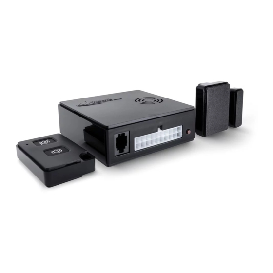
ECE regulation no. 10, revision 03. 3.3 Scope of delivery WiPro III central unit, connection cable, wireless remote control 868, wireless magnetic contact 868 with adhesive pads, fuse holder with fuse, status LED with con- nection cable, 1x warning sticker, installation manual and operating instructions T he scope of delivery varies for vehicle-specific sets. Depending on the vehicle type... - Page 18 Installation manual for WiPro III Page 17 3.4 Troubleshooting If the following section does not resolve or describe the problem, please contact our Technical Support Department: +49(0)431-66 66 811 Problem WiPro does not respond to the command from the remote key fob but the central locking system is working.
-
Page 19: Disposal Instructions
Installation manual for WiPro III Page 18 3.4 Disposal instructions When the unit is no longer in use, please do not dispose of it with household waste. Municipal recycling centres have suitable containers for the disposal of electronic equipment. Take the packaging materials to the recycling centre. - Page 20 Hersteller/Manufacturer Thitronik GmbH www.thitronik.de kontakt@thitronik.de Finkenweg 11 – 15 Te l .: +49 (0)4351 76744-0 D 24340 Eckernförde Fax: +49 (0)4351 76744-127 (Germany) 10R - 036873...
Need help?
Do you have a question about the WiPro III and is the answer not in the manual?
Questions and answers