
Related Manuals for Kilews SKP-BC40HL


Summary of Contents for Kilews SKP-BC40HL
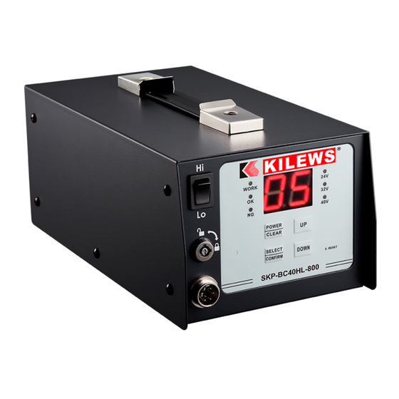
- Page 1 電動起子控制器操作手冊 OPERATION AND MAINTENANCE MANUAL SKP-BC40HL (VER:4.5) SKP-BC40HL-800 (VER:4.5) SKP-BC32HL-100 (VER:4.5) 奇力速工業股份有限公司 KILEWS INDUSTRIAL CO., LTD. http://www.kilews.com.tw Y2F125-21-001...
-
Page 2: Table Of Contents
NOTICE Metal Assembly Screwdrivers are designed for installing threaded fasteners in light industrial and appliance manufacturing applications. KILEWS is not responsible for customer modification of tools for applications on which KILEWS was not consulted. WARNIN Important safety information enclosed. Read all these instructions before placing tool in service or operation this tool and save these instructions. It is the responsibility of the employer to place the information in this manual into the hands of the operator. -
Page 3: Important Safety Instructions
Important Safety Instructions WARNING! Read all instructions Failure to follow all instructions listed below may result in electric shock fire and/or serious injure. The term "power tool" in all of the warning listed below refer to your mains operated (corded) power tool or battery operated (cordless) power tool. - Page 4 d) Store idle power tools out of reach of children and do not allow persons unfamiliar with the power tool or these instructions to operate the power tool. Power tools are dangerous in the hands of untrained users. e) Maintain power tools. Check for misalignment or binding of moving parts, breakage of parts and any other condition that may affect the power tools operation.
-
Page 5: Operations Cautions
Do not near oil, chemical materials or heated objects, also please be alert not to scratch the power cord by sharp object. This type of Controller can only be applied to KILEWS Electric Screwdriver with Counter. Do not use Electric Screwdriver Controller on other types of machinery. -
Page 6: Main Technical Parameters
Main Technical parameters SKP-BC32HL-100 SKP-BC40HL SKP-BC40HL-800 Model No (ver:4.5) (ver:4.5) (ver:4.5) Input Voltage AC 100-240V 50 / 60Hz AC 100-240V 50 / 60Hz AC 115/230V 50 / 60H Output Voltage DC 32V/ 24V DC 40V/ 32V/ 24V DC 40V/ 32V/ 24V... -
Page 7: Control Panel Specifications
Control panel specifications PARTS NAME PARTS NAME LED Indicator Down-Selecting Key HI / LO Speed Switch System Build-in Reset Key Key setting lock POWER/CLEAR Key 6Pin Connector Functional Selection / Confirm Key WORK Light Power point OK Light POWER SWITCH N.G Light Output voltage choice 24V Light... -
Page 8: Functions Of Keys On Panel
Functions of Keys on Panel: Description of function. Remarks When there is NG signal, POWER: Power Switch press CLEAR bottom to (1) Press and hold for 6 seconds that will turn off counter and other functions including 7 segments. clear the NG signal LED display. - Page 9 Note: Enter the setup: dt----- tt-----Sr----SA----Gr-----Rn (1) When the user press the dt/tt POWER + UP, panel displays dt:the time range between each screwing process. This function will be triggered after finish one dt, release POWER + UP to screwing process. If user doesn’t start next screwing process in this setting time range. The system show up values.
-
Page 10: I/O Inserting Hole
I/O Inserting Hole: Name In/Out Content wave pattern of signals Remark Output:DC +12V or +24V (Max:200mA) Default value:+24VDC Output 12 or 24 v dc (+12VDC need to custom modify) Automatically open CN2 and CN3 will be short MOS RELAY (default) +/- 40V, +/- 250mA There CN2~CN3 Output when finished fastening one... - Page 11 MOS RELAY I/O Terminal Connecting Diagram:(To take factory default: for example Output: Input:...
-
Page 12: Functional Dip Switch
Select OFF makes system automatically to recover from the setting count number. SW4:Switching Mode:Select ON means the external SENSOR need to have two signals been sent to SKP-BC40HL which stands for the fastener on operational process need to go through the sensor on machine table to identify the fastener has been removed from working table, and new fastener goes through another SENSOR for confirming the new fastener that has reached the working table. - Page 13 CONFIRM : Code Instruction Notations External sensor First external sensor to be confirmed. * When the SA is set to HI, the display SW2 (ON) + SW3 (OFF) + SW4 (OFF) "C1" ; if set is LO and will displayed "C.1 " The second external sensor to be confirmed.
-
Page 14: System Setting
※ If using three units of data only and let three units in cycles. It can set up "00" in counting number on U4, when SW6 switch ON, the system will automatically move in circle from U1~U3. System setting System procedure: SL<SELECT>SC<SELECT>At<SELECT>Ot<SELECT>Rc<SELECT>SP<SELECT>Ht<SELECT>... - Page 15 12、Presses SELECT to select then press UP/DOWN to change digits. The maximum digit is 9.9. Ut: Pre tightening time; any escaped time less than Ut will be counted as NG failure. 13、To press SELECT, the screen will show , push POWER key, adjust decimals , push UP/DOWN to increase or decrease number, the maximum can set up 9.99.
- Page 16 Data Chart: Ht/Lt mainly set up the period of time. If stop is within the set period, it means OK. In contrast, it will be (NG), as stop before Lt or after Ht. and should reconfirm whether wrong screws is taken. More precise requested means more correct Ht/Lt set-up should be.
-
Page 17: Simulated Learning
Simulated Learning 1、 The switch mode SW5 change into ON. ※When SW5 change to ON, it will force to enter simulated learning procedure, any function will not work. 2、 When it changes to ON, LED will flash. The user can set whether or not counting screws, starting slow-start. The simulated learning function will be turned on after these necessary condition confirming. - Page 18 CAUTION The use of other than genuine KILEWS replacement parts may Result in decreased tool performance and increased maintenance, and may invalidate all warranties. All repairs and maintenance of this tool and its word must be performed by an authorized service center.
-
Page 19: 一、重要安全說明事項
1.使用電動螺絲起子控制器說明書規定的電壓。 2.使用電源時請確定電流回路與安全開關裝置,並同時將地線接妥。 3.電動螺絲起子控制器勿置重物或堆積物品,且保持在適當的溫度與濕度狀態下工作。 4.勿將電動螺絲起子控制器放在通風不良之室內,或暴露在塵埃和金屬屑中 5.勿將電動螺絲起子控制器放在高溫潮濕的環境或易燃氣體的地方。 6.勿將電動螺絲起子控制器裝置在高處,應放于安全、平穩、固定的位置,以防止掉落的危險。 7.不可用電源線拉扯電動螺絲起子控制器,或將電源線從插座上猛拉開。 注 意 1、此控制器請搭配整組的專用電動起子 SKD-BN 與 SKD-BK 系列起子使用。 2、此控制器請配合 KILEWS SKD-BN 與 SKD-BK 系列計數器電動起子使用,控制器若搭配非 KILEWS 起子使用, 以及使用非 KILEWS 原廠的零配件維修,而造成控制器發生故障或品質不良,導致一切保證失效本廠恕不負責。 3、起子在進行中,若瞬間切換正反開關,機器將會啟動保護程式,起子將停止運轉。 4、起子運轉中,禁止切換高低速開關。 5、電源關閉後,需待 LED 燈熄滅後才可插拔 DC 連接線。 操 作 須 知 1、操作前請詳細閱讀操作手冊,並且按照安全規範操作此電源供應器。 2、當插入或拔開起子連接線和電源線之插頭時,需抓緊電纜線之插頭部分。 3、請將此電源供應器固定,避免因拉扯而造成危險。 4、請勿靠近油、化學物質或熱的物體,同時也注意不要讓電纜線在工作中刮磨到銳利的物品。... -
Page 20: 三、主要技術參數
主 要 技 術 參 數 SKP-BC32HL-100 SKP-BC40HL SKP-BC40HL-800 型 號 (ver:4.5) (ver:4.5) (ver:4.5) AC 100-240V 50 / 60Hz AC 100-240V 50 / 60Hz AC 115/230V 50 / 60H 輸 入 電 壓 DC 32V/ 24V DC 40V/ 32V/ 24V DC 40V/ 32V/ 24V 輸... -
Page 21: 四、面板規格
面 板 規 格 名稱 名稱 LED 顯示器 下選鍵 HI / LO 開關 內置系統重置鍵 計數器電源 / 清除鍵 鑰匙設定鎖 6PIN 連接頭 功能選擇 / 確認鍵 計數器工作燈 電源插座 OK 燈 電源開關 N.G 燈 輸出電壓選擇 24V 燈 指撥開關功能 *說明 32V 燈 I/O 插孔功能 *說明 40V 燈... -
Page 22: 面板按鍵功能說明
面板按鍵功能說明: 按 鍵 功 能 說 明 備 註 POWER:計數器電源開關 長按 6 秒左右,系統會關閉計數器、附加功能與 7 段 LED 顯示。 在關閉計數器的情況下再回復計數器,可按此鍵約 3 秒即可打開計數器功能。 CLEAR:回復開關 起子在計數進行中,計數器計數到一半,使用者需要回復清除,可按此鍵約 1 秒左右,即 可回復計數值,蜂鳴器響 1 聲。 在多循環模式下,長按 3 秒左右,即可回復到 U1 組的初始計數值,蜂鳴器響 2 聲。 參數設定模式時,此鍵為小數點切換鍵。 SELECT:功能選擇鍵 1.參考 任何時候長按此鍵 3 秒以上,即進入系統設定畫面,即: CONFIRM 模... - Page 23 進入設定畫面,即:dt----- tt-----Sr----SA----Gr-----Rn 註: (1)當 user 按 UP + dt/tt :工作時間提醒模式 POWER,面板顯示 dt, dt:每顆螺絲的間隔等待時間 (預設:00, 00~99,單位:秒) 放開 UP + POWER 就顯 示數值,在設定 dt 模式 當未鎖螺絲時此動作不會執行,當鎖一顆螺絲時,則會依照設定的時間等待,若超 過設定的時間內未有再鎖一顆的動作則會發出警告,display 會顯示"dt"字樣,直到 下,按"S"可以進去設定 "tt",重複 S 鍵動作可以 再鎖另一顆,依此類推。(以秒計算"01"=1 秒) 調整至後續功能 tt:設定總完成時間 (預設:00,00~99,單位:分) "Sr"→"SA"→"Gr"→"Rn" 設定時間內,要將所設定的螺絲全部鎖完,若在設定的時間內未將螺絲全部鎖完 display 會顯示"tt",直到將設定的螺絲全部鎖完即可解除。(以分計算"01"=1 分) (2) dt/ tt 是互斥設定,也...
-
Page 24: I/O 插孔功能說明
I/O 插孔功能說明 : 輸入 名稱 內容 備註 輸出 機器內置輸出電壓 DC +12V 或+24V (Max:200mA) 輸出+12 或 預設:+24VDC (+12VDC 可客製) +24VDC 自動開啟 MOS RELAY (預設) 鎖完一顆螺絲時 +/- 40V, +/- 250mA CN2~CN3 輸出 CN2、3 導通 4.5版 增加啟動訊號同步輸出亮燈。 (若要Open Collector電路,可客製) 自動開啟 MOS RELAY (預設) 當有錯誤操作時... - Page 25 端子接線簡圖: (以出廠設定值:MOS RELAY I/O 為例) 輸出: 輸入:...
-
Page 26: 指撥開關功能說明
決定起子是否動作。選擇 OFF 則表示不需要外接開關,計數不考慮外接開關來決定動作。 註:SA 設定值將影響 SW2=ON, SW4=OFF 的 SENSOR 驅動模式,詳細請參考 SA 設定值說明。 SW3 :計數回復方式:當計數螺絲到設定次數時,計數器必須回復到原先設定值,若選擇 ON 則表示 必須由面板確認(面板上"SELECT/CONFIRM") / 外部確認(CN11+CN14)來回復,否則機器 沒有確認的情況下電動起子則無法動作。選擇 OFF 則系統自動會自動回復。 SW4 :開關模式:選擇 ON,表示在外接的 SENSOR 必須要有兩個訊號給 SKP-BC40HL,則表示在 作業的製程上被鎖物必須經機台上的 SENSOR 確認有離開工作檯面上,而且新的被鎖物再 經由另一 SENSOR 確認有到此作業檯面上,如此兩個確認 SKP-BC40HL 才會動作起子才會 啟動。選擇 OFF 則表示只需要一個 SENSOR 來確認,確認被鎖物有離開此工作檯面電動起 子才會有動作。... - Page 27 CONFIRM 模式: 代號 說明 備註 外部感應開關 為一個開關 SENSOR 確認方式 當 SA 設定為 HI 時,顯示 SW2 (ON)+SW3(OFF)+SW4(OFF) "C1";若為 LO 時,顯示"C.1" 為二個開關 SENSOR 確認方式 SW2 (ON)+SW3(OFF)+SW4(ON) 外部感應開關 當發生錯誤時,SENSOR 需在感應,面板會顯示"Er",需再按 面板"CONFIRM"或外部確認(CN11+CN14 短路),將"Er"消除 面板上 CONFIRM 手動確認方式 面板 / 外部 CONFIRM SW3 (ON)+SW2(OFF)+SW4(OFF) 外部感應開關 +面板/外部 為一個開關...
-
Page 28: 五、系統設定方式
※若使用只有 3 組的數據,只想讓 3 組數據循環,可以在 U4 的計數次數 SC 設定為"00",如此在 SW6 切換 ON 時,系統將會自動從 U1~U3 循環 系統程序表單順序: SL→→SC→→At→→Ot→→Rc→→SP→→Ht→→Lt→→LL→→Ns→→Ut→→rt→→rr→→rS→→SAVE 系統設定步驟: 1、請將電源線接好,打開電源開關直到 LED 螢幕顯示數字即可。 2、請按 SELECT 鍵 3 秒以上,蜂鳴器會警示聲響,則螢幕會顯示 按 UP/DOWN 增加或減少數值, , 最多可以設定到 5 組。 3、按 SELECT 鍵,蜂鳴器會警示聲響,則螢幕會顯示 按 UP/DOWN 增加或減少數值,最多可以設 , 定到... - Page 29 14、按 SELECT,螢幕會顯示 按 POWER 鍵,調整小數點 ,按 UP/DOWN 增加或減少 , 數值,最多可以設定到 9.99。 rr:啟動反轉時間設定。 按 SELECT,螢幕會顯示 按 POWER 鍵,調整小數點 (0.10),按 UP/DOWN 增加或 15、 , 減少數值,最多可以設定到 9.99。 rS:啟動反轉後的停頓時間設定。 設置時間 原廠 功能名稱 功 能 解 釋 蜂鳴時間/發光二極體 及數值 設定值 01~05 數據組別 01~99 計數次數 0.0~9.9 自動回復時間...
- Page 30 Ht/Lt 示意圖: Ht/Lt 的時間主要是在設定時間範圍,若在設定的範圍內啟動到停止則顯示 OK 若螺絲在 Lt 設定 的時間之前停止或超過 Ht 的時間電動起子還沒停止,則表示螺絲在鎖的過程中不正常 (N.G),需 再次確認是否拿錯螺絲或者拿錯被鎖物,Ht/Lt 的時間設定的越精密則表示要求時 間越嚴格,此 系統 Lt 的時間默認為 0.00,若要修改則可到 SELECT 內容進行增加或減少。 ※電動起子啟動時間示意圖: STOP START 2.0 s 0.02 s 若起子在 Lt 前停止 起子超過 Lt 時間並且在 Ht 之前停止則系 若起子超過 Ht 尚未停止 統判定”OK” 螺絲鎖死或螺絲錯誤...
-
Page 31: 六、自動學習設定步驟
自動模擬學習設定步驟 1、 將模式選擇開關 SW5 切換 ON ※將 SW5 切至 ON 時,將強制進入自動模擬學習設定程序,任何功能將不起作用。 2、 切換 ON 時,LED 會閃爍讓使用者設定是否要計數幾顆螺絲、是否需要用到緩啟動,使用者必須先確定這些必 要條件才可以進行自動學習。 ------------------------------------------------------------------------------------------ 設定完成後,LED 會顯示 0.0,使用者可以測試鎖螺絲動作,當起子啟動時,LED 會跟著計數,當起子剎車停止 動作時,就是螺絲鎖附完成的時間,使用者可以進行多次測試,直到滿意為止,使用者可以將 DIP SW5 開關切 至 OFF 狀態,如此系統將自動設定 Ht 的時間。(註 Lt 自動設定為零) 3、 若使用者認為數值尚不理想,再將 DIP SW5 切至 OFF 狀態時,可按住 SELECT 3 秒以上,進去選單畫面進行修 改。...
Need help?
Do you have a question about the SKP-BC40HL and is the answer not in the manual?
Questions and answers