Advertisement
Quick Links
PROPER USE GUIDELINES
Cumulative trauma disorders can result from the prolonged use of manually powered hand tools. Hand tools are intended for occasional
use and low-volume applications. A wide selection of powered application equipment is available for extended-use production operations.
The SDE-SA hand tool is a commercial-grade tool. Product crimped with this tool meets the wire barrel crimp height requirement for hand
tools in the appropriate 114 application specification but might not comply with other feature parameters of the specification.
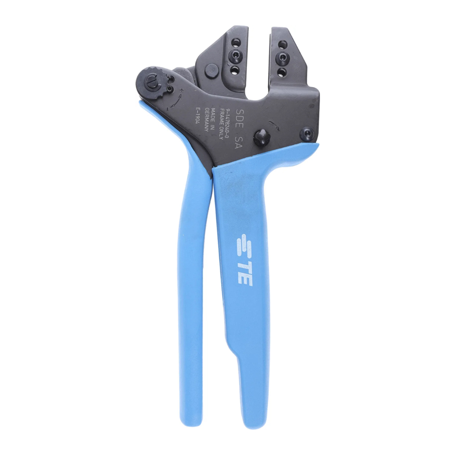
Figure 1: SDE-SA Commercial Hand Tool Assembly 2373648-1 with Die Assembly 2373648-2
1
2
3
4
© 2022 TE Connectivity Ltd. family of companies.
All Rights Reserved.
TE Connectivity, TE connectivity (logo), and TE (logo) are trademarks. Other logos, product, and/or company names may be trademarks of their respective owners.
SDE-SA Commercial Hand Tool Assembly
PN 2373648-1 with
Die Assembly PN 2373648-2
Die set 2373648-2
Wire crimper (upper die)
Wire indenter (lower die)
Stationary jaw
PRODUCT INFORMATION 1-800-522-6752
5
Moving jaw
Ratchet adjustment wheel
6
Handle
7
8
Die-retaining screws (2)
This controlled document is subject to change.
For latest revision and Regional Customer Service,
visit our website at www.te.com.
Instruction Sheet
408-35314
6 SEP 2022 Rev A
1 of 9
Advertisement

Subscribe to Our Youtube Channel
Related Manuals for TE Connectivity SDE-SA


Summary of Contents for TE Connectivity SDE-SA
- Page 1 A wide selection of powered application equipment is available for extended-use production operations. The SDE-SA hand tool is a commercial-grade tool. Product crimped with this tool meets the wire barrel crimp height requirement for hand tools in the appropriate 114 application specification but might not comply with other feature parameters of the specification.
- Page 2 408- 35143) and the die assembly listed in Figure 1. This tool is used to crimp the terminal part numbers listed in Table 1. Table 1: Crimping specifications Wire SDE-SA assembly Product family (SOLISTRAND) tool Size AWG Strip length mm [in.]...
- Page 3 408-35314 3. INSTALLING THE DIE SET AND LOCATOR ASSEMBLY 1. Open the tool handles. 2. Remove the two die-retaining screws from the tool jaws (see Figure 1). 3. Insert the wire anvil in the moving jaw of the tool frame with their chamfered sides and the marked surfaces facing outward.
- Page 4 408-35314 5. CRIMPING NOTE The tool is provided with a crimp adjustment feature. Initially, the crimp height should be verified as specified in Figure 3. Refer to section 7, INSPECTING THE CRIMP HEIGHT, and section 8, ADJUSTING THE RATCHET, to verify crimp height before using the tool.
- Page 5 408-35314 6. INSPECTING THE CRIMP Inspect crimped terminals and splices by checking the features shown in Figure 3. Poor crimps (Figure 4) can be avoided by carefully following the procedures provided in section 5, and by following the tool maintenance procedures provided in section 9.
- Page 6 7. INSPECTING THE CRIMP HEIGHT This inspection requires the use of plug gages conforming to the dimensions provided in Figure 5 and Table 2. TE Connectivity does not manufacture or market these gages. Figure 5: Recommended plug gage design 1 GO dimension 4 50.8 [2.00] minimum (typical)
- Page 7 408-35314 4. Align the NO GO element and try to insert it straight into the same crimping chamber. The NO GO element can start entry, but it must not pass completely through the crimping chamber (Figure 7). Figure 7: NO GO element ...
- Page 8 408-35314 8. ADJUSTING THE RATCHET The ratchet is preset prior to shipment, but it is important to verify the crimp height using a micrometer or caliper. Use and wear can cause the tool to go out of adjustment. Inspect the crimp height and adjust the ratchet, if necessary, on a regular basis.
-
Page 9: Maintenance And Inspection
Shop TE link at the top of the page. Call 800-522-6752. Write to: CUSTOMER SERVICE (038-035) TE CONNECTIVITY CORPORATION PO BOX 3608 HARRISBURG PA 17105-3608 For customer repair services, call 800-522-6752. 11. REVISION SUMMARY Revisions to this instruction sheet include:... - Page 10 Mouser Electronics Authorized Distributor Click to View Pricing, Inventory, Delivery & Lifecycle Information: TE Connectivity 2373648-1...
Need help?
Do you have a question about the SDE-SA and is the answer not in the manual?
Questions and answers