Table of Contents
Advertisement
Available languages
Available languages
Quick Links
Advertisement
Chapters
Table of Contents

Related Manuals for Siemens SIMATIC NET SCALANCE X005TS


Summary of Contents for Siemens SIMATIC NET SCALANCE X005TS
- Page 1 Vorwort Einführung Netztopolo e gi n Produkteigens ften SIMATIC NET Industrial Ethernet Montage und Wartung SCALANCE X005TS Hinweise zu den Umwelttests Inbetriebnahmehandbuch Literaturverzeichnis Maßzeichnung 06/2010 A2B00060684C Deutsch/English English...
- Page 2 Marken sein, deren Benutzung durch Dritte für deren Zwecke die Rechte der Inhaber verletzen können. Copyright Siemens AG 2010. All rights reserved. Haftungsausschluss Weitergabe sowie Vervielfältigung dieser Unterlage, Verwertung und Mitteilung ihres Wir haben den Inhalt der Druckschrift auf Übereinstimmung mit der beschriebenen Hard- Inhalts ist nicht gestattet, soweit nicht ausdrücklich zugestanden.
-
Page 3: Table Of Contents
ha verzeichnis Vorw ort ..............................1-1 Vorwort............................1-1 Einf ührung .............................. 2-1 Einführung..........................2-1 Netztopol ogien............................3-1 Netztopologien ........................... 3-1 Prod ukteigenschaften ..........................4-1 SCALANCE X005TS Lieferumfang ................... 4-1 SCALANCE X005TS Auspacken und Prüfen ................ -
Page 5: Vorwort
Switches SCALANCE X005TS (Transportation System). Gültigkeitsbereich dieser Inbetriebnahmeanleitung Diese Inbetriebnahmeanleitung ist für folgende Geräte gültig: SIMATIC NET SCALANCE X005TS 6GK5005-0BA00-1CA3 Weiterführende Dokumentation Im Handbuch „SIMATIC NET Industrial Ethernet Twisted Pair- und Fiber Optic Netze“ erhalten Sie zusätzliche Hinweise zu weiteren SIMATIC NET-Produkt... -
Page 7: Einführung
Einführung 2.1 Einführung Dieses Kapitel gibt Ihnen einen Überblick über die Funktion des u nmanaged Industrial Ethernet Entry Level Switches SCALANCE X005TS Was ist möglich? Der Switch SCALANCE X005TS ermöglicht den kostengünstigen Aufbau von kleinen Industrial Ethernet Linien- bzw. Sternstrukturen mit Switching Fun ktionalität. -
Page 9: Netztopologien
Netztopologien 3.1 Netztopologien Die Switching Technologie ermöglicht den Aufbau ausgedehnter Netz e mit mehreren Teilnehmern und vereinfacht die Netzerweiterung. Welche Netztopologien können realisiert werden? Mit dem Gerät SCALANCE X005TS können Linien- und Sterntopologien realisiert werden. Linientopologie Bild 3-1 Linientopologie mit SCALANCE X005TS Industrial Ethernet SCALANCE X005TS Inbetriebnahmehandbuch, A2B00060684C, 06/2010... - Page 10 Netztopologien 3.1 Netztopologien Sterntopologie Bild 3-2 Sterntopologie mit SCALANCE X005TS Industrial Ethernet SCALANCE X005TS Inbetriebnahmehandbuch, A2B00060684C, 06/2010...
-
Page 11: Produkteigenschaften
Produkteigenschaften SCALANCE X005TS Lieferumfang Was wird mit dem SCALANCE X005TS ausgelief ert? • Gerät SCALANCE X005TS • 2-poliger steckbarer Klemmenblo • Inbetriebnahmehandbuch (dieses Dokument) 4.2 SCALANCE X005TS Auspacken und Prüfen Auspac en, Pr üfen 1. Überprüfen Sie das Paket auf Vollständigkeit 2. -
Page 12: Scalance X005Ts Produkteigenschaften
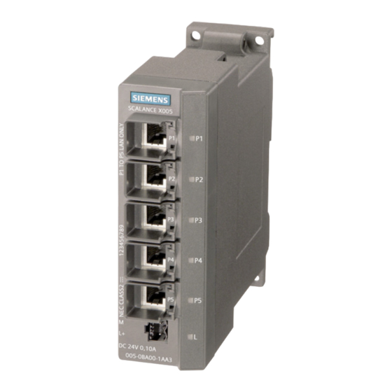
Produkteigenschaften 4.3 SCALANCE X005TS Produkteigenschaften 4.3 SCALANCE X005TS Produkteigenschaften Anschlussm öglichkeiten Der SCALANCE X005TS verfügt über fünf RJ45 Buchsen für den Anschluss von Endgeräten oder weiterer Netzsegmente. Bild 4-1 SCALANCE X005TS Industrial Ethernet SCALANCE X005TS Inbetriebnahmehandbuch, A2B00060684C, 06/2010... -
Page 13: Scalance X005Ts Tp-Schnittstellen
Produkteigenschaften 4.4 SCALANCE X005TS TP-Schnittstellen 4.4 SCAL ANCE X005TS TP-Schnittstellen Steckerbelegung RJ45-Buchse Bild Steckerbelegung RJ45 Pinnummer Belegung Pin 8 n. c. Pin 7 n. c. Pin 6 Pin 5 n. c. Pin 4 n. c. Pin 2 Pin 1 Beim SCALANCE X005TS sind die Twisted Pair-S chnittstellen, als RJ45-Buchse mit MDI-X Belegung (Medium Dependent Interface–Autocrossover) einer Netzkomponente ausgeführt. - Page 14 Produkteigenschaften 4.4 SCALANCE X005TS TP-Schnittstellen dass ein automatisches Konfigurieren unterschiedlicher Geräte mö glich ist. Das Autonegotiation-Verfahren ermöglicht es zwei Komponenten, di e an einem Link-Segment ange schlossen sind, untereinander Parameter auszutauschen und sich mit Hilfe dieser rameter auf die jeweils unterstützten Eckwerte der Kommunikation einzustellen. Hinweis Geräte, die kein Autonegotation unterstützen müssen auf 100 MBit / Halbduplex bzw.
-
Page 15: Scalance X005Ts Spannungsversorgung
Produkteigenschaften 4.5 SCALANCE X005TS Spannungsversorgung 4.5 SCALANCE X005TS Spannungsversorgung Spannungsv ersorgung Der Anschluss der Spannungsversorgung erfolgt über einen 2-poligen steckbaren Klemmenblock. Die Spannungsversorgung ist hochohmig mit dem Gehäuse verbunden, um einen erdfreien Aufbau zu ermöglichen. Die Spannungsversorgung ist potentialgebunden. Bild 4-3 Spannungsversorgung Bild 4-4 Steckerbelegung Pinnummer Belegung... -
Page 16: Scalance X005Ts Technische Daten
Produkteigenschaften 4.7 SCALANCE X005TS Technische Daten Portzustandsanzeige (grün/gelbe L EDs) r Zustand der Schni ttstellen w ird über fünf LEDs signalisiert: Zustand Bedeutung Port 1 bis 5 LED leuchtet grün TP-Link vorhanden, kein Datenempfang Port 1 bis 5 LED leuchtet gelb TP-Link vorhanden, Daten empfangen am TP Port Port 1 bis 5 LED blinkt gelb Testphase, während Power on... - Page 17 Produkteigenschaften 4.7 SCALANCE X005TS Technische Daten Zulässige Umgebungsbedingungen / EMV Betriebstemperatur -40°C bi s +65°C Lager-/Transporttemperatur -40°C bis +80°C Relative Feuchte im Betrieb ‹ 95% (nicht kondensierend) Betriebshöhe 2000 m bei max 46 °C U mbebungstemperatur 3000 m bei max. 40 °C Umgebungstemperatur Störfestigkeit EN 61000-6-2 (Class A)
- Page 18 Produkteigenschaften 4.7 SCALANCE X005TS Technische Daten Hinweis Die Anzahl der angeschlossenen Industrial Ethernet Switches SCALA NCE X beeinflusst die Telegrammdurchlaufzeit. Beim Durchlauf eines Telegramms durch den SCALANCE X00 5TS wird dieses durch die Store&Forward Funktion des Switch verzögert - bei 64 Byt e Telegrammlänge um circa 10 µs (bei 100 Mbit/s) - bei 1500 Byte Telegrammlänge um circa 130 µs (bei 100 Mbit/s) Das heißt, je mehr SCALANCE X005TS durchlaufen werden, desto höher ist die...
-
Page 19: Montage Und Wartung
Montage und Wartung 5.1 Mont Montagearten Der SCALANCE X005TS lässt mehrere Montagearten zu: • M ontage auf 35 mm DIN Hutschiene • Montage auf einer SIMATIC S7-300 Profilschiene • Wandmontage inweis Beachten Sie bei Installation und Betrieb die Aufbaurichtlinien und Sicherheitshinweise, die in dieser Beschreibung sowie im Handbuch SIMATIC NET Indu strial Ethernet Twisted... -
Page 20: Hutschienenmontage
Montage und Wartung 5.2 Hutschienenmontage 5.2 Hutschienenmontage Montage Montieren Sie den SCALANCE X005TS auf einer 35 mm Hutschiene nach DIN EN 50022. 1. Hängen Sie die obere Rastführung des Geräts in die Hutschiene ein und drücken Sie es nach unten gegen die Hutschiene bis zum Einrasten. 2. -
Page 21: Profilschienenmontage
Montage und Wartung 5.3 Profilschienenmontage Bild 5-2 SCALANCE X005TS Demontage von einer DIN-Hutschiene (35 mm) Profilschienenmontage tage auf einer SIMATIC S7-300 Profilschiene 1. Hängen Sie die Gehäuseführung an der Oberseite des SCALAN CE-Gehäuses in die S7-Profilschiene ein. 2. Verschrauben Sie das Gerät SCALANCE X005TS an der Unterseite der Profilschiene. 3. -
Page 22: Wandmontage
Montage und Wartung 5.4 Wandmontage Bild 5-3 SCALANCE X005TS Montage auf einer SIMATIC S7-300-Profilschiene 5.4 W andmontage Wandmontage 1. Verwenden Sie vier Wandd übel mit 6 mm Durchmesser und 30 mm Länge. 2. Verwenden Sie zur Befestigung Schrauben mit 3,5 mm Durchmesser und 40 mm Länge. Für genaue Maße beachten Sie bitte die Maßzeichnungen im Kapitel „Maßzeichnung“... -
Page 23: Erdung
Montage und Wartung 5.5 Erdung 5.5 Erdung Hutschienenmontage Die Erdung erfolgt über die Hutschiene. S7-Profilsc hiene Die Erdung erfolgt über die Geräterückseite und die Halssch raube. Wandmonta Die Erdung erfolgt durch die Befestigungsschraube über die lackfreie Bohrung. Beachte n Sie bitte, dass der SCALANCE X005TS über eine Befestigungsschraube möglichst niederohmig geerdet werden muss. -
Page 24: Montage Des Ie Fc Standard Cable
Montage und Wartung 5.6 Montage des IE FC Standard Cable 5.6 Montage des IE FC Standard Cable So montiere n Sie den IE FC RJ45 Plug 180 an das IE FC Standard Cable Die Hinweise zur Montage entnehmen Sie bitte der Anweisung, d ie dem IE FC RJ45 Plug 180 beilie Die robusten und industriegerechten Teilnehmeranschlüsse mit PROFINET-konformen... - Page 25 Montage und Wartung 5.6 Montage des IE FC Standard Cable Stecken des IE FC RJ45 Plug 180 Stecken Sie den IE FC RJ45 Plug 180 bis zum Verrasten in die Twisted Pair Schnittstelle des SCALANCE X005TS bzw. der Geräte der Produktlinien SCALANCE X-100 bzw. X-200 Bild 5-5 Stecken des IE FC RJ45 Plug 180 Der Haltekragen an der TP-Schnittstelle des SCALANCE X005TS gewährleistet durch den...
-
Page 26: Wartung
RJ45 Plug 180 aus der Twisted Pair Buchse ziehen. 5.7 Wartung Wartung Bitte senden Sie das Gerät im Fehlerfall an Ihre SIEMENS Dienststelle zur Reparatur ein. Eine Reparatur vor Ort ist nicht möglich. Industrial Ethernet SCALANCE X005TS Inbetriebnahmehandbuch, A2B00060684C, 06/2010... -
Page 27: Hinweise Zu Den Umwelttests
MATIC NET Industrial Ethernet TP- und Fiber Optic Netze“ /1/ beschrieben sind. Konformitätserklärung Die EG-Konformitätserklärung wird gemäß den oben genannten EG-Richtlinien für die zuständigen Behörden zur Verfügung gehalten bei: Siemens Aktiengesellschaft Industry Sector Industry Automation Division Industrielle Kommunikation (I IA SC IC) Postfach 4848 D-90026 Nürnberg... -
Page 28: Hinweise Zur E1/E1-Zulassung
Hinweise zu den Umwelttests 6.2 Hinweise zur e1/E1-Zulassung Hinweise für Hersteller von Maschinen Das Pr odukt ist keine Maschine im Sinne der EG-Richtlinie Maschinen. Es gibt deshalb für dieses Produkt keine Konformitätserklärung bezüglich der EG-Richtli nie Maschinen 89/392/EWK. Ist das Produkt Teil der Ausrüstung einer Maschine, muss es vom Maschinenhersteller in das Verfahren zur Ko nformitätserklärung einbezogen werden. -
Page 29: Literaturverzeichnis
1. SIMATIC NET Industrial Twisted Pair- and Fiber Optic Net ze, Ausgabe 05/2001 Bestellnummern: 6GK1970-1BA10-0AA0 d eutsch 6GK1970-1BA10-0AA1 englisch 6GK1970-1BA10-0AA2 französisch 6GK1970-1BA10-0AA4 italienisch 2. Weiterführende Informationen zum SCALANCE-System sind im Internet unter www.siemens.com/scalance verfügbar Industrial Ethernet SCALANCE X005TS Inbetriebnahmehandbuch, A2B00060684C, 06/2010... -
Page 31: Maßzeichnung
Maßzeichnung Bild 8-1 Bohrschablone Industrial Ethernet SCALANCE X005TS Inbetriebnahmehandbuch, A2B00060684C, 06/2010... - Page 33 Preface Introduction Network Topo logi Product Chara ristics SIMATIC NET Industrial Ethernet Installation and Maintenance SCALANCE X005TS Notes on the environmental tests Commissioning Manual References Dimension Drawing 06/2010 A2B00060648C English...
- Page 34 Trademarks ll designations marked with ® are reg istered tr ademarks of Siemens AG. Other designations in this d ocum entation might be tra demarks which, if use by third parties for their...
- Page 35 able of Contents Pref ace ..............................1-1 Preface............................1-1 Intro duction............................. 2-1 Introduction ..........................2-1 Netw ork Topologies ..........................3-1 Network Topologies ........................3-1 Prod uct Characteristics........................... 4-1 Components of the SCALANCE X005TS Product..............
-
Page 37: Preface
SCALANCE X005TS (Transportation System). Validity of this Com missioning Manual This commissioning manual is valid for the following devices: SIMATIC NET SCALANCE X005TS 6GK5005-0BA00-1CA3 Further Documentation The “SIMATIC NET Industrial Ethernet Twisted Pair and Fiber Optic Ne tworks” manual... -
Page 39: Introduction
Introduction 2.1 Introduction This chapter provides you with an overview of the functions of the unman aged Industrial Ethernet entry level switch SCALANCE X005TS. What Is Possible? The SCALANCE X005TS switch enables the cost-effective installation of small Industrial Ethernet bus or star structures with switching functionality. The devices are d esigned for installation in a switchin g cubicle. -
Page 41: Network Topologies
Network Topologies 3.1 Network Topologies Switching technology allows extensive networks to be set up wit h numerous nodes and simplifies network expansion. Which network topologies can be implemented? With the SCALANCE X005TS device, bus and star topologies can be implemented. Bus Topology Figure 3-1 Bus topology with SCALANCE X005TS... - Page 42 Network Topologies 3.1 Network Topologies Star Topology Figure 3-2 Star topology with SCALANCE X005TS Industrial Ethernet SCALANCE X005TS Commissioning Manual, A2B00060648C, 06/2010...
-
Page 43: Product Characteristics
Product Characteristics Components of the SCA LANCE X005TS Product What ships with th e SCALANCE X005TS? • SCALANCE X005TS device • 2-pin plug-in terminal block • Commissioning manual (this document) 4.2 SCALANCE X005TS Unpacking and Checking Unpacking, Ch ecking 1. Make sure that the package is complete 2. -
Page 44: Scalance X005Ts Product Characteristics
Product Characteristics 4.3 SCALANCE X005TS Product Characteristics 4.3 SCALANCE X005TS Product Characteristics Possible Atta chments SCALANCE X005TS features five RJ-45 jacks for the connection of DTEs or other network segments. Figure 4-1 SCALANCE X005TS Industrial Ethernet SCALANCE X005TS Commissioning Manual, A2B00060648C, 06/2010... -
Page 45: Scalance X005Ts Tp Ports
Product Characteristics 4.4 SCALANCE X005TS TP Ports 4.4 SCAL ANCE X005TS TP Ports Connector Pinout RJ-45 jack Figu re 4-2 RJ-45 connector pinout Pin number Pinout Pin 8 Pin 7 Pin 6 Pin 5 Pin 4 Pin 3 Pin 2 Pin 1 On SCALANCE X005TS, the twisted pair ports are implemented as RJ-45 jacks with MDI-X... - Page 46 Product Characteristics 4.4 SCALANCE X005TS TP Ports port of a partner device allowing automatic configuration of different types of device. With autonegotiation, two components connected to a link segment can exchange parameters and set themselves to match the supported communication functionality. Note Devices not supporting autonegotiation must be set to 100 Mbps/ half duplex or 10 Mbps hal duple...
-
Page 47: Scalance X005Ts Power Supply
Product Characteristics 4.5 SCALANCE X005TS Power Supply 4.5 SCALANCE X005TS Power Supply Power Supp The power supply is connected using a 2-pin plug-in terminal block. The power supply is connected over a high resistance with the enclosure to allow an ungrounded setup. The power supply is non-floating. -
Page 48: Scalance X005Ts Technical Specifications
Product Characteristics 4.7 SCALANCE X005TS Technical Specifications Port status indicator (green/yellow LEDs) he status of the ports is indica ted by five LEDs: Status Meaning Port 1 to 5 LED lit green TP link exists, no data reception Port 1 to 5 LED lit yellow TP link exists, data received at TP port Port 1 to 5 LED flashes yellow Test phase during power on... - Page 49 Product Characteristics 4.7 SCALANCE X005TS Technical Specifications Permitted Environmental Conditions / EMC Operating temperature -40°C to +65°C Storage/transport temperature -40°C to +80°C Relative humidity in operation ‹ 95% (no condensation) Operating altitude 2000 m at max 46 °C amb ient temperature 3000 m at max.
- Page 50 Product Characteristics 4.7 SCALANCE X005TS Technical Specifications Note The number of connected SCALANCE X Industrial Ethernet switches influ ences the frame propagation time. When a frame passes through SCALANCE X005TS, it is delayed by the sto re and forward function of the switch: - With a 64 byte fram e length by approx.
-
Page 51: Installation And Maintenance
Installation and Maintenance 5.1 Insta llation es of installation SCALANCE X005TS can be installed in various ways: Installation on a 35 mm DIN rail • • Installation on a SIMATIC S7-300 standard rail • Wall mounting Note When installing and operating the device, keep to the installation instructions and safet y-related notices as described here and in the SIMATIC NET Industrial Ethernet... -
Page 52: Installation On A Din Rail
Installation and Maintenance 5.2 Installation on a DIN Rail 5.2 In stallation on a DIN Rail Installation Install the SCALANCE X005TS on a 35 mm DIN rail complying with DIN EN 50022. 1. Place the upper catch of the device over the top of the rail and then push in the lower part of the device against the rail until it clips into place. -
Page 53: Installation On A Standard Rail
Installation and Maintenance 5.3 Installation on a Standard Rail Figure 5-2 SCALANCE X005TS removing from a DIN rail (35 mm) Installation on a Standard Rail Inst allation on a SIMATIC S7-300 Standa rd Rail 1. Place the upper guide at the top of the SCALANCE housing in the S7 standard rail. -
Page 54: Wall Mounting
Installation and Maintenance 5.4 Wall Mounting Figure 5-3 SCALANCE X005TS installation on a SIMATIC S7-300 standard rail 5.4 W all Mounting Wall Mounting 1. U se four wall plugs (6 mm diameter and 30 mm long). 2. To attach the device, use screws with a diameter of 3.5 mm and a length of 40 mm. For exact dimensions, please observe the dimension drawings in the Chapter “Dimension Drawing”... -
Page 55: Grounding
Installation and Maintenance 5.5 Grounding 5.5 Grounding Installation on a DIN Rail The device is grounded over the DIN rail. S7 Standa rd Rail The device is grounded over its rear panel and the neck collar screw. Wall Mounti The device is grounded by the securing screw in the unpainted hole. Please note that SCALANCE X005TS must be grounded over one securing screw with minimum resistance. -
Page 56: Assembling The Ie Fc Standard Cable
Installation and Maintenance 5.6 Assembling the IE FC Standard Cable 5.6 Assembling the IE FC Standard Cable Assemble th e IE FC RJ-45 plug 180 and the IE FC standard cable as follows For information on the assembly, please refer to the instructions that shi p with the IE FC RJ-45 plug 180. - Page 57 Installation and Maintenance 5.6 Assembling the IE FC Standard Cable Plugging the IE FC RJ-45 Plug 180 Plug the IE FC RJ-45 plug 180 in the twisted pair port of SCALANCE X005TS or of the devices of the product lines SCALANCE X-100 or X-200 until it snaps into place. Figure 5-5 Plugging the IE FC RJ-45 plug 180 Due to the closing shape and the latching with the PROFINET-compliant connector IE FC...
-
Page 58: Maintenance
2.5 mm screwdriver. Subsequently you can unplug the IE FC RJ-45 plug 180 from the twisted pair port. 5.7 Maintenance Maintenance If a fault develops, please send the device to your SIEMENS service center for repair. Repairs on-site are not possible. Industrial Ethernet SCALANCE X005TS Commissioning Manual, A2B00060648C, 06/2010... -
Page 59: Notes On The Environmental Tests
Fiber Optic Networks” /1/ when installing and operating the device. Conformity Certificates The EC Declaration of Conformity is available for the responsible authorities according to the above-mentioned EC Directive at the following address: Siemens Aktiengesellschaft Industry Sector Industry Automation Division Industrielle Kommunikation (I IA SC IC) Postfach 4848 D-90026 Nürnberg... -
Page 60: Notes On The E1/E1 Approval
Notes on the environmental tests 6.2 Notes on the e1/E1 approval Notes for Ma nufacturers of Machines This product is not a machine in the sense of the EU directive on mach ines. There is therefore no declaration of conformity for the EU d irective on machines 89/392/EEC. -
Page 61: References
1. SIMATIC NET Industrial Twisted Pair and Fiber Optic Net works, Edition 05/2001 Order numbers: 6GK1970-1BA10-0AA0 G erman 6GK1970-1BA10-0AA1 English 6GK1970-1BA10-0AA2 French 6GK1970-1BA10-0AA4 Italian 2. You will find further information on the SCALANCE system on the Internet at www.siemens.com/scalance Industrial Ethernet SCALANCE X005TS Commissioning Manual, A2B00060648C, 06/2010... -
Page 63: Dimension Drawing
Dimension Drawing Figure 8-1 Drilling template Industrial Ethernet SCALANCE X005TS Commissioning Manual, A2B00060648C, 06/2010...
Need help?
Do you have a question about the SIMATIC NET SCALANCE X005TS and is the answer not in the manual?
Questions and answers