Table of Contents
Advertisement
Quick Links
Advertisement
Table of Contents

Related Manuals for UTAH SCIENTIFIC BPS-2020


Summary of Contents for UTAH SCIENTIFIC BPS-2020
- Page 1 BPS-2020 / Bypass Switcher System Overview and Operations...
- Page 2 Information contained in this guide is subject to change without notice or obligation. While every effort has been made to ensure that the information is accurate as of the publication date, Utah Scientific, Inc. assumes no liability for errors or omissions. In addition, Utah Scientific, Inc. assumes no responsibility for damages resulting from the use of this guide.
- Page 3 Following the provisions of the Directive(s) of the Council of the European Union: • EMC Directive 89/336/EED • Low Voltage Electrical Directive 72/23/EEC Utah Scientific, Inc. hereby declares that the product specified above conforms to the above Directive(s) and Standard(s). Setup and Operations Guide...
- Page 4 Route power cords and other cables so they won’t be damaged. • The AC receptacle (socket) should be located near the equipment and be easily accessible. • Disconnect power before cleaning. Do not use any liquid or aerosol cleaner - use only a damp cloth. BPS-2020...
- Page 5 • Dangerous voltages exist at several points in this product. To avoid personal injury, do not touch exposed conductors and components while power is on. Do not insert anything into either of the systems two-power supply cavities with power connected. •...
- Page 6 Company Information Utah Scientific, Incorporated 4750 Wiley Post Way, Suite 150 Salt Lake City, Utah 84116-2878 U.S.A. • Telephone: +1 (801) 575-8801 • FAX: +1 (801) 537-3098 • Technical Services (voice): +1 (800) 447-7204 • Technical Services (FAX): +1 (801) 537-3069 •...
- Page 7 Warranty Policies Hardware Warranty Utah Scientific, Inc. warrants to the original purchaser that the Utah Scientific hardware is free from defects in materials and workmanship and will perform substantially in accordance with the accompanying written materials under normal use and service for a period of ten (10) years from the date of shipment.
- Page 8 No liability for consequential damages. To the maximum extent permitted by applicable law, in no event shall Utah Scientific or its suppliers be liable for any damages whatsoever (including without limitation, damages for loss of business profits, business interruption, loss...
-
Page 9: Table Of Contents
Power Supplies ................1-9 Crosspoint/Control Card (121188-1, -2) ........1-10 Crosspoint/Control Card - continued ........1-13 BPS-2020 Video DA Card ............1-14 BPS-2020 Video 8x1 Input Card ..........1-14 BPS-2020 AES Crosspoint ............1-14 BPS-2020 Analog Audio Crosspoint ..........1-14 BPS-2020 Deluxe Audio Crosspoint (121178-1/2) .....1-15 BPS-2020 Clean Quiet Module ..........1-16... - Page 10 Audio Input/Output Connectors ........... A-3 Output Connectors Pinout ........... A-4 Appendix B - BPS-2020 Break Out Addendum In This Addendum ..............B-1 Using the UTAH-200 Breakout Panel on the BPS-2020 ... B-2 Appendix C Debug Port C-1 Description ..................C-1 Connector ..................C-1 Terminal Emulation Settings ............
-
Page 11: Bps-2020 (Bypass Switcher)
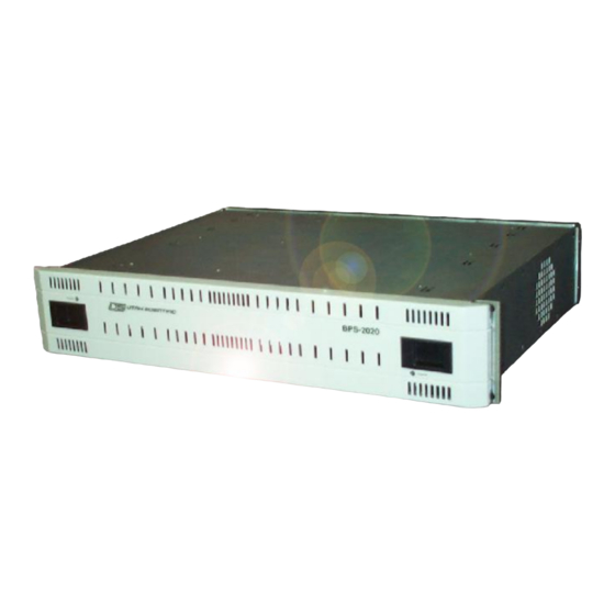
BPS-2020 (Bypass Switcher) Receiving the System - Unpacking The BPS-2020 consists of a 2 rack unit electronics frame and one or more control panels. Power cards are provided for each device. The 1 rack unit control panel can exist as the following versions; the BPS-8 (eight button control panel), the BPS-16 (multi-channel control panel), or the BPS-16S (16 source control panel). -
Page 12: General Overview
General Overview How the System is Used The BPS-2020 is intended to be downstream of all processing equipment in a standard TV station environment. The Audio/Video output would directly feed the transmission system of a station. The system can also be used in any other AV switching application. -
Page 13: Video Card Variations
General Overview Video Card Variations There are two different video crosspoint cards. This card is the heart of the system from a control standpoint, and orchestrates all system activities. The 121188-2 card is an 8 input crosspoint, while the 121188-1 is a 16 input crosspoint. -
Page 14: System Installation
BPS-2020 (Bypass Switcher) System Installation Rack Mounting The 2 Rack Unit electronics frame should be installed near the master control switcher in the main audio/video path of the system. The 1 Rack Unit control panel should be installed in the Master Control room where it is easily accessible to the operator. -
Page 15: Multichannel Connections
The cable then loops through the BPS-2020 chassis on the two “BPS-NET” RJ-45 connectors. The open connector on the last BPS-2020 should be terminated with USI part number 65324-04. Note that each BPS-2020 must be addressed with a dipswitch on the video crosspoint card. Chapter 1... -
Page 16: Video Connections
BPS-2020 (Bypass Switcher) Video Connections VIDEO (INVERTED ) INPUT O UT IN 1 IN 2 IN 3 IN 4 IN 5 IN 6 IN 7 IN 8 LO O P O UT Figure 1-3. 8-Input systems Standard video ports include 8 inputs and 1 dual output connection. Optionally, a DA card can be purchased that provides an active loop output for each input. -
Page 17: Operation Of The Bps-Cp-16
Operation is very straight forward. The left bank of 8 buttons selects the BPS-2020 chassis you wish to control. When a channel is selected, the right bank of buttons will show its current status. A cycling lamp pattern will indicate that the designated address is not communicating. -
Page 18: Card Installation
121188-2 8x1 crosspoint, and the 121186-1 should only be used with the 121188-1 16 Input crosspoint. Slots 3, 4 – either the BPS-2020 Digital Audio (121184-1) crosspoint, the BPS-2020 Analog Audio Crosspoint (121183-1), or the Deluxe Audio crosspoint can be placed here. -
Page 19: Pcb Mounted Controls And Indicators
PCB Mounted Controls and Indicators PCB Mounted Controls and Indicators Power Supplies • The power supplies are calibrated at the factory. No field adjustment is necessary. • The supplies have Red LED’s that indicate failure of the 5V, 3.3V, +-12V, integral fan and overtemperature. They also have a bi-color LED that is green when all other failure leds are off, and red when one or more of the other alarms trip. -
Page 20: Crosspoint/Control Card (121188-1, -2)
BPS-2020 (Bypass Switcher) Crosspoint/Control Card (121188-1, -2) BPS-2020 Video Crosspoint/Control Card. This card is the heart of the BPS-2020 system, as it consolidates all control functions as well as the video switching. There are numerous controls on it. Indicators: Clean/Quiet... - Page 21 = input 1, all on = input 16. Controls: • Dipswitch SW1. ~ Switches 1,2 and 3 form the address of the BPS-2020 when used in a networked environment. All address’s must be unique in a networked environment. These switches are unused in a non-networked environment.
- Page 22 BPS-2020 (Bypass Switcher) Important! On BPS-2020 crosspoint cards running software version 2.06C or earlier, the functions of switch 4 and 5 on SW1 are swapped. Switch 4 is for the baud rate, while Switch 5 corresponds to the protocol. Refer to Appendix C to confirm the software version.
-
Page 23: Crosspoint/Control Card - Continued
PCB Mounted Controls and Indicators Crosspoint/Control Card - continued Clean Quiet sub-module RS 232/422 Jumpers Figure 1-9. CQ Module and RS 232/422 positions Chapter 1 1-13... -
Page 24: Bps-2020 Video Da Card
• Controls – Jumper J19 selects between SD and HD edge rates. Set this according to the type of video you are passing thru the system. BPS-2020 Video 8x1 Input Card Indicators: • Green - Power OK LED • Controls - None... -
Page 25: Bps-2020 Deluxe Audio Crosspoint (121178-1/2)
PCB Mounted Controls and Indicators BPS-2020 Deluxe Audio Crosspoint (121178-1/2) Loop Lock Ref OK Power OK 3.3V 1.2V/2.5V • This module includes the following LED indicators to aid in the evaluating the board and signal conditions. ~ LOOP LCK - Related to the phase lock loop clock system that is implemented on this board. -
Page 26: Bps-2020 Clean Quiet Module
~ VCO – Voltage Controlled Oscillator input level. ~ TAKE – Pulsed high at the time of the input switch. BPS-2020 Clean Quiet Module • DS-1 Scangate Active LED. Will flash periodically. • DS-2 Configuration OK. Indicates the circuitry on this module has properly powered up and is ready for use. - Page 27 PCB Mounted Controls and Indicators Chapter 1 1-17...
- Page 28 BPS-2020 (Bypass Switcher) 1-18 BPS-2020...
-
Page 29: Operation
Initial System Power up Operation Initial System Power up Apply power to the 2RU electronics chassis by connecting power cords to both IEC Inlets. Remove the front cover and verify the following – • That both power supplies show the large LED Green and no error LED’s. -
Page 30: Control Panel Usage
The control panel contains 8 buttons with integral LED’s. Dim - Backlight Bright - Currently routed source. If communication from the panel to the BPS-2020 frame is interrupted, the lamps will cycle back and forth indicating no communication. Control Options •... -
Page 31: Initial System Configuration
Once connected, press the space bar to get the menu screen. The terminal should look like this – ************************************************ BPS-2020 8/16 System Monitor MENU - V2.00 ************************************************ 0-7 = Make Switches. G = Genlock Part Status. - Page 32 CQ Active LED on the video crosspoint card and passing the video thru the clean quiet module. Normal Clean/Quiet operation is indicated by having the CQ active, REF OK and VCO LOCKED LED’s on the Video Crosspoint card illuminated. BPS-2020 Operations...
-
Page 33: Other Operational Scenarios
Other operational Scenarios Other operational Scenarios Forcing the bypass relay The system bypass relay connects input 1 to the output BNC closest to it when Bypass mode is active. Bypass is active when the system power is off or a major fault is detected. It can also be enabled from the terminal or the serial port if required for maintenance. -
Page 34: Rear Panel Description
PANEL Port. This port connects to the standard remote control panel in a standalone system, and may connect to nothing in a networked system. The cable is a standard straight thru CAT5 cable terminated in RJ-45 connectors. Length should not exceed 1000 feet. BPS-2020 Operations... - Page 35 Rear Panel Description • Serial Port. This is a switchable 9 pin female D-SUB port used for remote control from PC or automation systems. ~ Format – RS-232 or RS-422 switchable on controller card. ~ Baud Rate – 19.2K or 38.4 K baud, switchable on controller board.
- Page 36 Active Loop thru inputs – If ordered, an optional DA card provides a buffered representation of the inputs at the 8 ‘LOOP OUT’ BNC’s. • Outputs. ~ Two output BNC’s are present. They are the normal and complement output of the currently routed source. BPS-2020 Operations...
-
Page 37: Specifications
Overview Specifications Overview 1. Mechanical • 2RU electronics frame. 2. Power Requirement • Redundant power supplies with separate power cords. • 100-234 VAC input at .5 Amps 3. Video • Routes SMPTE 259, 292 or non-standard sources from 1.5Mb/Sec to 1.485 Gb/Sec. All pertinent SMPTE specs are met. - Page 38 ± 7V (DC + Peak Signal) Common Mode Rejection Per AES-3, Section 6.3.5 (1997) Output Impedance - Balanced 110¾ ±20%, 100 kHz. to 6.144 MHz Output Amplitude 2.0 VPP into 110?, minimum Nominal Rise / Fall Times 25 nano seconds BPS-2020...
- Page 39 Overview Common Mode Rejection >30 dB, DC to 6 MHz Sample Rate 48 kHz Intrinsic Jitter < 0.025 UI Peak, w/700 Hz. HPFApplies to -discrete AES outputs. Output Phasing with respect ± 2.5% (± 9º) of Frame Inter- to DARS val.Applies to -discrete AES outputs.
-
Page 40: Power Supplies
Isolated 5-12 V inputs. Connection is via12 pin barrier strip. • 8 Tally Outputs are available. These are TTL high true indications that a particular source is selected. Connection is via DB9. Power Supplies • Standard Dual Redundant Hot-Swappable power supplies. BPS-2020... -
Page 41: Appendix A - Rear Panel Pinout Detail
RS-422 Mode • Pin 2 = Transmit Data Out - • Pin 7 = Transmit Data Out + • Pin 3 = Receive Data In + • Pin 8 = Receive Data In - • Pin 5 = Ground BPS-2020... -
Page 42: Tally Output
Rear Panel Pinout Detail Tally Output This 9 Pin D-SUB connector is used for connection to a tally system to show which input of the BPS is active. The signal polarity is low = off, high = on. Lows are <.5V and highs are > 3V. •... -
Page 43: Audio Connections
Output Input Audio Input/Output Connectors Input Connectors Pinout (Note: Inputs 1-8 become 9-16 on the bottom board and connectors if configured as a BPS-2020-16) • Pins 9, 10, 19-26 - Ground. • Pin 1,11 Input 1 +,- •... -
Page 44: Output Connectors Pinout
Rear Panel Pinout Detail Output Connectors Pinout • Pins 3-9, 10, 13-18, 19-26 - Ground. • Pin 1,11 Output +,- for CH1-2 or 3-4. • Pin 2,12 Output +,- for CH5-6 or 7-8. • *Pin 8,18 DARS +,- for System AES Sync. (*Note: CH 1-2 connector only. -
Page 45: Appendix B - Bps-2020 Break Out Addendum
This addendum provides important information about using the UT-200 style breakout panel on the BPS-2020 system. Reference the document titled “Installation Procedure for the Utah-200 Breakout Panel and Cable Assembly.” Also reference the “BPS-2020 / Bypass Switcher” manual for the details of the audio pinouts. BPS-2020... -
Page 46: Using The Utah-200 Breakout Panel On The Bps-2020
This section provides details about the physical INPUT connections of the UTAH-200 breakout panel when used with the BPS-2020. • The BPS-2020 supports eight inputs. Each audio input can have up to eight channels (four AES streams) of digital audio. -
Page 47: Appendix C Debug Port
The P1 connector on the crosspoint card is a diagnostic port used for system upgrades, configuration and debugging. It is an RS-232 port and must be communicated to with a suitable terminal emulation program installed on a PC. Utah Scientific provides a program called TeraTerm as part of its standard documentation package. Connector To ease the connection, an adapter from DB9 to RJ-45 is provided (USI Part Number 140000-8, “UT-400”). -
Page 48: Terminal Emulation Settings
Appendix C Debug Port Terminal Emulation Settings The following settings should be made in order to communicate with the BPS-2020. ·Baud Rate–38400. ·Data Bits - 8. ·Stop Bits - 1. ·Parity - None. ·Handshake - XON/XOFF. Verifying Communication The Diagnostic Port reports every switch that is made, and responds to commands entered into the terminal. -
Page 49: Appendix D - Firmware Update Procedure
The firmware on the Video Crosspoint Card will provide the ability to field reprogram the DSP. Before you attempt to upgrade software in the card, consult with Utah Scientific Customer Service to ensure you are upgrading to the proper version for your application. - Page 50 Firmware Update Procedure 2. Open TeraTerm on your PC. • Set it up for COM1, 38400 baud, 8 data, 1 stop with no parity bits, and XON/XOFF handshake. 3. Press the reset button on the 121188-1. Press ENTER immediately after you see “©...
- Page 51 B- 2 operational overview 2- 1 Audio Connections 1-5, 2-7, A- 3 PANEL Port 2- 6 Baud Rate 2- 7 BPS-2020 mounted controls and indicators 1- 9 video DA card 1-14 Power Requirement 3- 1 BPS-NET ports 2- 6...
Need help?
Do you have a question about the BPS-2020 and is the answer not in the manual?
Questions and answers