Table of Contents
Advertisement
Quick Links
Advertisement
Table of Contents
Troubleshooting

Related Manuals for UTAH SCIENTIFIC UTAH-200


Summary of Contents for UTAH SCIENTIFIC UTAH-200
- Page 1 UTAH-200 Compact Routing Switcher Menu Cancel Take UTAH-200 User's Guide...
- Page 2 Date: January 2001 • Printed in U.S.A. Copyrights and Trademarks © 1999 Utah Scientific , Inc. All rights reserved. Any use or reproduction of this guide’s contents without the prior written consent of Utah Scientific , Inc. is strictly prohibited. •...
- Page 3 Following the provisions of the Directive(s) of the Council of the European Union: • EMC Directive 89/336/EED • Low Voltage Electrical Directive 72/23/EEC Utah Scientific , Inc. hereby declares that the product specified above conforms to the above Directive(s) and Standard(s).
- Page 4 Important Safeguards and Notices This section provides important safety guidelines for both the Operator and Service Personnel. Specific warnings and cautions are found throughout the guide where they apply, but may not appear here. Please read and follow the important safety information, noting especially those instructions related to risk of fire, electric shock or injury to persons.
- Page 5 When the adjacent symbol is indicated on the chassis, please refer to the manual for additional information. • For the UTAH-200 chassis, refer to the “Connecting and Disconnecting Power” section in Chapter 2 for important information regarding the chassis power connector.
- Page 6 Company Information 4750 Wiley Post Way Salt Lake City, Utah 84116-2878 USA • Telephone: +1 (801) 575-8801 • Fax: +1 (801) 537-3098 • +1 (800) 447-7204 Customer Support (Voice): • Customer Support (Fax): +1 (801) 537-3009 • E-mail (General Info): info@utsci.com •...
-
Page 7: Table Of Contents
Terms ..........................1-4 Company Information ......................1-6 Routing Switcher Basics ..................... 1-7 Switching Matrix....................1-8 Signal Levels......................1-9 Introducing the UTAH-200....................1-10 System Configurations ..................1-12 Control Panel ........................1-16 Rear Control Panel......................1-18 Blank Panel........................1-20 Front Chassis ........................1-21 Rear Chassis ........................ - Page 8 Saving a Panel Configuration File................ 4-55 Clearing Locks and Protects....................4-55 Changing PC-to-Controller Communications..............4-56 Upgrading Controller Software ..................4-56 Upgrading Control Panel Software..................4-57 Error Reporting ........................ 4-58 RMS-200 Error Log ......................4-59 Keyboard Shortcuts ......................4-60 ii • • Contents UTAH-200 User's Guide...
- Page 9 Error Message List....................5-49 Panel Error Messages......................5-50 Panel Errors ......................5-50 U-Net Errors....................... 5-50 Toggle Mode Indication ..................5-51 Panel Program Errors..................5-51 Reset Panel Software ......................5-52 Clear Panel Software......................5-52 Contents • • iii UTAH-200 User's Guide...
- Page 10 Digital Audio ........................8-4 Control ..........................8-5 Power ..........................8-5 Alarms ..........................8-6 Physical..........................8-6 Regulatory .......................... 8-7 U-Net Cabling........................8-8 Pinouts..........................8-10 U-Net Connector Pinouts ..................8-10 SMPTE Alarm Connector Pinouts............... 8-11 iv • • Contents UTAH-200 User's Guide...
- Page 11 RS422 Connector Pinouts ................... 8-11 RS232 Connector Pinouts ................... 8-12 Ethernet Connector Pinouts................. 8-12 MX Bus Connector Pinouts................. 8-14 Appendix D. Remote Diagnostics In This Appendix......................... 9-1 Using the UTAH-200 Controller Diagnostic Port ..............9-1 Index 10-1 Contents • • v UTAH-200 User's Guide...
- Page 12 • • Contents UTAH-200 User's Guide...
- Page 13 . 1-11, 7-19 connector .....1-25, 1-27 input connectors ....1-29 installation ......2-14 input installation ....2-38 pinouts ........8-11 input installation, analog ..2-25 power supply ......6-5 specifications ......8-6 Index • • 10-1 UTAH-200 User's Guide...
- Page 14 Check, data ....4-23, 4-34, 4-38 Breakaway ......1-7, 1-11 Checking fuses ......2-44 function ........5-3 Checkout, hardware ....2-45 icon ......5-9, 5-10, 5-26 Choose destination dialog ....3-5 take menu ......5-14 CLEAR ........5-31 take notes ......5-19 10-2 • • Index UTAH-200 User's Guide...
- Page 15 ......1-28 redundant ....1-21, 1-22 power ........1-19 reset switch ......1-22 RS232 ........1-26 slot, bay 1 ......1-22 RS422 ........1-26 slot, bay 2 ......1-23 sync ........1-25 Index • • 10-3 UTAH-200 User's Guide...
- Page 16 ......5-15 Digital video scroll, lock/protect ....5-32 backplane ......1-28 setup options ....5-37, 5-41 board detail ......7-25 take ........5-11 data reclock jumpers .....7-27 Detail analog audio board ....7-7 10-4 • • Index UTAH-200 User's Guide...
- Page 17 ......2-13 lock/protect ....5-30, 5-32 Exit ..........4-4 Dst table Expansion connectors ..7-8, 7-19 get matrix ....4-32, 4-38 Extension set matrix .....4-32, 4-38 .sct ........... 4-5 DTR ..........1-4 .xyp ......... 4-6 Index • • 10-5 UTAH-200 User's Guide...
- Page 18 ..1-29 src table ...... 4-32, 4-34 assignment matrix, setup ..4-48 Ground, frame ....1-26, 1-27 assignment tab ......4-25 digital audio connectors ..1-29 equalization ......7-10 gain compensation jumpers ..7-10 Halt upgrade ..... 4-13, 4-14 10-6 • • Index UTAH-200 User's Guide...
- Page 19 ......7-24 SC-2 ........2-7 Ethernet board ...... 7-30 SC-3 ........2-7 PLL sync ....... 7-21 UTAH-200, large system ..2-7 signal present ......7-22 Interface board ....1-22, 1-23 valid AES reference ....7-21 analog ........7-13 valid AES signal ....7-20 digital ........
- Page 20 ....5-25 functional ......1-35 destination enabled ....5-26 interconnect cable ....2-6 destination monitor ....5-25 pinouts ........8-14 direct take ......5-20 terminator ....1-26, 1-27, 2-6 edit .......... 4-7 error message ......5-48 file 4-4 10-8 • • Index UTAH-200 User's Guide...
- Page 21 ....4-6 overview ......... 5-2 program error ......5-51 RMS-200 ......4-42 reset software ......5-52 UTAH-200 ......5-1, 5-6 save configuration file ..4-55 Option, equalization ....7-14 source function buttons ..4-33 Options icon ......... 5-9 source matrix ......4-34 Output ..........
- Page 22 ......4-42 Programming prerequisites ......3-3 all follow take ....... 5-12 run 3-9 breakaway take ..... 5-16 serial communications ....3-9 destination monitor take ..5-27 shortcut ......3-7, 3-9 lock/protect ......5-33 software installation ....3-4 10-10 • • Index UTAH-200 User's Guide...
- Page 23 ........5-46 SC-3 ........... 1-10 Shortcut .........3-7, 3-9 interconnection ....... 2-7 Scroll breakaway ....5-14, 5-15 destination ..5-11, 5-15, 5-32 lock/protect ..5-30, 5-31, 5-32 destination monitor ....5-27 knob .......1-17, 5-5 preselect ........ 5-11 Index • • 10-11 UTAH-200 User's Guide...
- Page 24 ....4-5 analog audio connectors ..8-3 save configuration ....4-5 analog video ......8-2 setup ........1-10 control ........8-5 voltage ........1-10 digital audio ......8-4 digital video ......8-4 physical ........8-6 10-12 • • Index UTAH-200 User's Guide...
- Page 25 ......1-10 setup options ......5-44 diagnostic port ...... 3-11 Tool bar .........4-3, 4-9 frame ........1-10 Tool-tip help ........ 1-2 functional diagram ....1-34 TRACK ......5-12, 5-27 introduction ......1-10 icon ......5-12, 5-27 Index • • 10-13 UTAH-200 User's Guide...
- Page 26 ....... 4-15 status ......4-3, 4-15 Voltage ........1-10 VTR ..........1-4 Watchdog timer ......7-3 Welcome dialog ......3-4 Window menu ......4-8 Windows ........1-3 95, NT ........3-3 conventions ......3-3 10-14 • • Index UTAH-200 User's Guide...
-
Page 27: Introduction
Introduction In This Guide This guide provides instructions for installing, configuring and operating the UTAH-200 compact routing switcher. The following chapters and appendices are included: • Chapter 1, “Introduction” summarizes the guide and describes the hardware and software components of the system. -
Page 28: How To Use This Guide
Once you’re familiar with the product, start with the Index when you need assistance on a specific subject. On-Line Help The RMS-200 application includes an on-line help file and tool-tip help fields. The on-line help file provides the entire contents of the UTAH-200 User’s Guide, plus a complete index. • On-line Help In the Menu Bar, click Help, then Contents to display the help file’s table of contents. -
Page 29: Conventions
For example: Press Take to perform ... Take • On the UTAH-200’s LCD Display, labels and commands are indicated in bold-faced upper and lower case text, using a sans- serif font. For example: Press PRE to pre-select the ... -
Page 30: Abbreviations
“Frame” refers to a single UTAH-200 electronics chassis, configured as an audio-only, video-only, or audio/video routing switcher matrix. • “Main Frame” refers to the one frame in a UTAH-200 system that contains the CPU (controller) board. The main frame also contains one (or more) signal levels. •... - Page 31 • “Signal Level” refers to the specific type of audio/video element that a frame is capable of routing. The UTAH-200 system can switch up to eight signal levels, which can be any combination of the following:...
-
Page 32: Company Information
(the panel on which the protect was entered). Similar to Locks, a protect can also be unlocked by any user from a control panel (or cleared from the RMS-200). Company Information Utah Scientific Video Systems, Inc. 4750 Wiley Post Way Salt Lake City, Utah 84116-2878 USA •... -
Page 33: Routing Switcher Basics
• Routing switchers can switch many signal levels simultaneously — up to eight in the case of the UTAH-200. For example: – A simple route connects one signal level from one source device (such as a VTR) to one destination device (such as a video monitor). -
Page 34: Switching Matrix
(as a source), and record the next moment (as a destination). • Even though the matrix size shown above is 10x10, in the UTAH-200 you can configure two different matrices: 16x16 and 32x32. 1-8 • • Introduction UTAH-200 User's Guide... -
Page 35: Signal Levels
Signal Levels A “signal level” represents one of many specific types of audio or video elements that a routing switcher is capable of handling. The UTAH-200 can switch up to eight signal levels, which can be any combination of the following: •... -
Page 36: Introducing The Utah-200
Introducing the UTAH-200 The UTAH-200 is a powerful and compact routing switcher system designed to meet the needs of users who require flexible control, multi- format routing and expansion capability. Using a small and cost-effective package, the UTAH-200 is well-suited for small matrix routing requirements, master control routing or as an ideal “migration”... - Page 37 Please contact Customer Support for details. For additional information and installation instructions for the Video Equalization option, refer to the “Video Equalization Option” section in Appendix B. Introduction • • 1-11 UTAH-200 User's Guide...
-
Page 38: System Configurations
32x32. The keyword is simplicity, with all facets of the product — installation, configuration, operation, and expansion. The UTAH-200 system is modular, with the ability to interconnect frames for easy expansion. Each frame consists of one 2-RU chassis that includes bays for crosspoint matrices, CPU boards, and power supplies. - Page 39 In the above configuration, one power supply is used for the video, and a different supply is used for the audio. The configuration can not support redundant power supplies. Either supply, however, can be installed in either position. Introduction • • 1-13 UTAH-200 User's Guide...
- Page 40 Bay 2 (with connectors for 32 inputs and outputs). This chassis is thus factory-configured for a field upgrade to 32x32 Stereo Analog Audio. 1-14 • • Introduction UTAH-200 User's Guide...
- Page 41 Bay 1 (with connectors for 32 inputs and outputs), and a second audio backplane is installed on the rear of Bay 2 (with connectors for 32 inputs and outputs). Frame 2 does not include a CPU board. Introduction • • 1-15 UTAH-200 User's Guide...
-
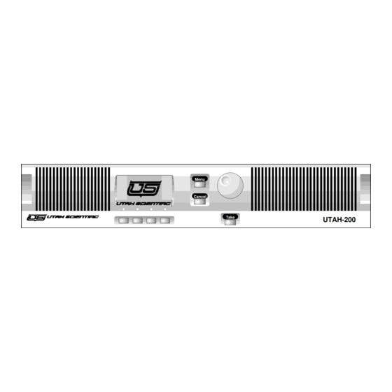
Page 42: Control Panel
Control Panel The figure below illustrates the UTAH-200’s control panel, which is designed for simplicity and ease of operation. • When used locally, the panel snaps onto the front of the Main Frame, with a simple ribbon-cable connection between the two. - Page 43 CD players, tape players, and speaker systems with ease. • When control panels are daisy-chained together, the total length of the entire cable run can not exceed 1000 feet. Introduction • • 1-17 UTAH-200 User's Guide...
-
Page 44: Rear Control Panel
(not shown above) that shields the panel’s circuitry. If you need to adjust the DIP Switch or the Contrast control, remove the protective cover — and be sure to replace it when all adjustments are complete. 1-18 • • Introduction UTAH-200 User's Guide... - Page 45 In Chapter 2, refer to the “Setting Control Panel ID Switches” section for instructions. 4) Reset Press the Reset switch to reset the control panel’s CPU. 5) Contrast Use the Contrast control to adjust the contrast of the LCD display. Introduction • • 1-19 UTAH-200 User's Guide...
-
Page 46: Blank Panel
On Main Frames that do not have a control panel installed. • On all Auxiliary frames. The figure below illustrates the UTAH-200’s snap-on Blank Panel: UTAH-200 1) Air Vents — the vertical grilles on each side of the blank panel are intakes for the frame’s air flow. -
Page 47: Front Chassis
If an audio backplane is installed, slot 1 can house a 16x16 audio matrix board. 3) Bay 1 Crosspoint Slot 2 If a video backplane is installed, slot 2 can house a 16x16 video matrix board. Introduction • • 1-21 UTAH-200 User's Guide... - Page 48 If a video backplane is installed, slot 2 can house one 16x16 video matrix. • If an audio backplane is installed, slots 1 and 3 can each house one 16x16 audio matrix. • The bay can not house an audio and video matrix simultaneously. 1-22 • • Introduction UTAH-200 User's Guide...
- Page 49 If the crosspoint matrix cards in Bay 1 and Bay 2 are not identical, one slot must contain a supply rated for the first matrix’s voltage, while the second slot must contain a supply rated for the second matrix’s voltage requirements. Introduction • • 1-23 UTAH-200 User's Guide...
-
Page 50: Rear Chassis
The Control Block is available in two different configurations: • Master Control Block — this configuration (as shown above) is standard on all UTAH-200 “Main Frames” — those containing CPU boards. The control block includes all the connectors necessary for system communication and frame interconnection. -
Page 51: Master Control Block Connectors
Alarm connector provides a relay-closure output that can be connected to your facility’s alarm monitoring system. In the event of an alarm, the frame can be taken out of service and repaired without disruption to other functional frames. Introduction • • 1-25 UTAH-200 User's Guide... - Page 52 The Ethernet connector (RJ-45) is used for communications with the RMS-200 application, and for other forms of remote communications with the UTAH-200. The system uses category five, 10Base-T Ethernet cable. For initial setup of the IP Address, the diagnostic port is required. Contact Customer Support for details on supported Ethernet commands.
-
Page 53: Slave Control Block Connectors
4) Frame Ground A hex-nut and washer are provided for strapping the frame to ground, if required. Note that proper installation of the frame in your equipment rack will automatically ground the chassis. Introduction • • 1-27 UTAH-200 User's Guide... -
Page 54: Video Backplane
The bottom DIP switch sets the signal level address for the matrix, and also sets the expansion input offset. In Chapter 2, refer to the “Setting Frame ID Switches” section for DIP switch instructions. 1-28 • • Introduction UTAH-200 User's Guide... -
Page 55: Audio Backplane
Two connectors are provided for audio inputs 0-15: • J8, inputs 0-7 • J7, inputs 8-15 These inputs can be used as follows: Analog Audio: • Mono 32x32: inputs 0-15 • Stereo 16x16: inputs 0-15 (channel 1) Introduction • • 1-29 UTAH-200 User's Guide... - Page 56 These outputs can be used as follows: Analog Audio: • Mono 32x32: outputs 16-31 • Stereo 16x16: outputs 0-15 (channel 2) Digital Audio: • 32x32: AES outputs 16-31 (channels 1/2) • 16x16: AES outputs 0-15 (channels 3/4) 1-30 • • Introduction UTAH-200 User's Guide...
- Page 57 Synchronous version of the Digital Audio Board is installed, and when jumper JP1 is installed on the Synchronous module. In Appendix B, see the “Digital Audio Board” section for instructions on setting the jumper position. Introduction • • 1-31 UTAH-200 User's Guide...
- Page 58 Digital Audio — with a digital audio board installed, the input is active only when the Synchronous version of the Digital Audio Board is installed, and when jumper JP1 is installed on the Synchronous module. 1-32 • • Introduction UTAH-200 User's Guide...
- Page 59 2, see the “Audio Connector Wiring Charts” section for connector pinouts. Note In a previous version of UTAH-200 hardware, a different analog audio backplane was used which included a 3-pin terminal for the Analog Monitor Matrix Connector. For details on this connector, please contact Customer Support.
-
Page 60: Functional Diagram
Functional Diagram The figure below illustrates a functional block diagram of the UTAH-200 system. UTAH-200 Controller UTAH-200 Controller (Main or "Active") (Backup or "Standby") • CPU • CPU • Interfaces • Interfaces High-Speed Link Router Status via "read-back" • Current configuration I/O Interface •... - Page 61 Windows 95 or NT. Now that you are familiar with the basic functionality, capabilities, and components of the UTAH-200 system, please continue with chapter 2, “Hardware Installation.” Introduction • • 1-35...
- Page 62 1-36 • • Introduction UTAH-200 User's Guide...
-
Page 63: Hardware Installation
Hardware Installation In This Chapter This chapter provides instructions for installing the UTAH-200 in your facility. The following topics are covered: • Unpacking and Inspection • Installing Hardware • Installing Physical Equipment • Interconnecting Frames • Interconnecting Control Panels •... -
Page 64: Unpacking And Inspection
Unpacking and Inspection When you receive your UTAH-200 system, inspect each shipping carton for signs of damage. Contact your dealer and the shipper immediately if you suspect any damage has occurred during shipping. Check the contents of each box to be sure that all parts are included. If any items are missing, contact your dealer immediately. - Page 65 Channel 5/6 UTAH-200 Signal Level Five: AES Digital Audio Channel 7/8 UTAH-200 2. Once the layout is determined, remove the “snap-on” front cover from each UTAH-200 frame, and set the cover aside. Hardware Installation • • 2-3 UTAH-200 User's Guide...
- Page 66 (if required). The stud is located at the left edge of the control block. Note that proper installation of the frame in your rack automatically grounds the chassis. This completes the installation of each routing switcher frame. 2-4 • • Hardware Installation UTAH-200 User's Guide...
- Page 67 • The self-contained control panel Use the following steps to install each control panel: 1. Determine the location for each UTAH-200 control panel in your facility. Ensure that each location is within 5 feet of an AC outlet. This distance is the length of the DC power cord.
-
Page 68: Interconnecting Frames
UTAH-200 system. 6. On the last Auxiliary Frame in the chain, connect the supplied MX Bus Terminator plug to the open MX Bus connector. This completes the interconnection of each routing switcher frame. 2-6 • • Hardware Installation UTAH-200 User's Guide... - Page 69 Interconnecting the UTAH-200 in a Larger System The UTAH-200 can operate in conjunction with (and can be controlled by) other Utah Scientific routers and peripherals using the SC-2 and SC-3 control systems. Note In this type of configuration, the UTAH-200 would be installed without a Main Frame.
-
Page 70: Interconnecting Control Panels
Frame’s U-Net connector to either U-Net connector on your first control panel. 3. Using another U-Net Cable, connect the first control panel’s open U-Net connector to either U-Net connector on your second control panel. 2-8 • • Hardware Installation UTAH-200 User's Guide... -
Page 71: Installing Communication Cables
RS232 Com Port (running the (sending RMS-200 the proper application) protocol) Use the following steps to install RS232 communications: 1. In the Control Block of your system’s “Main Frame,” locate the RS232 connector. Hardware Installation • • 2-9 UTAH-200 User's Guide... - Page 72 RS232 port. Note By default, the RS232 port is enabled on the UTAH-200, with the following parameters: Protocol (RMS), Baud Rate (38400), Data Bits (8), Stop Bits (1), Parity (None).
- Page 73 RS422 port. Note By default, the RS422 port is enabled on the UTAH-200 with the following parameters: Protocol (UDI), Baud Rate (9600), Data Bits (8), Stop Bits (1), Parity (None), Take Echo (On), Change Echo (On), Refresh (Off), Xon/Xoff (Off).
- Page 74 Installing Ethernet The UTAH-200 uses Ethernet to communicate with a PC equipped with the RMS-200 application, or to communicate with another device in your facility that uses Utah Scientific’s proprietary RCP-3 Ethernet protocol. There are two ways to install Ethernet: •...
- Page 75 If your PC is already connected to a different hub, consult with your facility’s Network Administrator to ensure that your PC and the UTAH-200 are both using the same Subnet Mask. This completes the procedure for installing network hub cables.
- Page 76 2. Using a customer supplied cable (typically, twisted pair), connect the Main Frame’s Alarm+ terminal to the Alarm+ terminals on each UTAH-200 frame in your system. Connect the Main Frame’s Alarm– terminal to each frame’s Alarm– terminal in the same manner. Be sure to connect all + and –...
-
Page 77: Connecting The Reference Signal
Note If your facility has an existing alarm circuit, add the UTAH-200 frames to the existing chain using the diagram above as an interconnection example. -
Page 78: Setting Frame Id Switches
(a). Ensure that the last device in the loop is terminated with a 75 Ohm terminator. 4. If the UTAH-200 frame is the last device in the loop, terminate the open Sync connector with a 75 Ohm terminator (customer supplied) as shown above in the diagram’s example (b). - Page 79 5. Repeat for every board in each of your frames. Note Individual switches within a group can be combined to form different offsets (e.g., switches 2 and 3 can be up [on] to form an output of 96). Hardware Installation • • 2-17 UTAH-200 User's Guide...
- Page 80 1. On paper, determine the number that you want to assign to each signal level. For example: digital video: router level 1 analog audio channel 1: router level 2 analog audio channel 2: router level 3 2-18 • • Hardware Installation UTAH-200 User's Guide...
- Page 81 3. Repeat step 2 for every board in each of your frames. Note You can have a maximum of eight router levels in the UTAH-200 system (in the range 0 - 7). The other router level positions are provided for compatibility with other UTAH routers. Refer to the SC-3 User’s Guide for complete details.
-
Page 82: Setting Control Panel Id Switches
Once you have set the ID number, make a note of the number on your Panel Information Chart. Repeat the procedure for each control panel in your system. In chapter 4, refer to the “Panel Information Chart” section for a sample chart. 2-20 • • Hardware Installation UTAH-200 User's Guide... -
Page 83: Installing Audio/Video Signals
Installing Audio/Video Signals This section provides instructions for installing audio and video signals from each of your facility’s devices to (and from) the UTAH-200 router. Note the following important points: • Routing Switchers have large numbers of inputs and outputs, and care is needed to plan your cabling. - Page 84 Ensure that all video cables (both ends) are clearly labeled with the signal that it carries (e.g., VTR1 Vid Out). • All UTAH-200 video inputs use BNC 75 Ohm single-ended connectors. • Input connectors are arranged in two rows of eight connectors each, and numbered (from right to left) 0 through 15, or 16 through 31 —...
- Page 85 • Signal Timing: For synchronous switching, all video signals should be timed to arrive at the same time at the UTAH-200’s inputs. Note All video inputs (except the Reference loop) are internally terminated (75Ω). It is not permissible to loop video inputs using a BNC “T”...
- Page 86 Recommended Cable Max. Cable Length Termination Analog Audio Belden 8451 (twisted pair) Internal, optional 600Ω Digital Audio Belden 9180 (or better) 300 feet (balanced) Internal Belden 8251 (or better) 1000 feet (unbalanced) Internal 2-24 • • Hardware Installation UTAH-200 User's Guide...
- Page 87 Inputs can be connected directly to the backplane. A connector kit (part number 65362-4) consisting of eight 26-pin high- density male connectors and back shells is available from Utah Scientific. Please contact your Utah Scientific representative for details. • Inputs can be connected to an optional Analog Breakout Panel.
- Page 88 Outputs can be connected directly to the backplane. A connector kit (part number 65362-4) consisting of eight 26-pin high-density male connectors and back shells is available from Utah Scientific. Contact your Utah Scientific representative for details. • Outputs can be connected to an optional Analog Breakout Panel.
- Page 89 LCD display. • The lower MON output (adjacent to J7) is used as follows: If a single 16x16 analog audio board is installed in a bay, the lower MON output switches outputs 0-15. Hardware Installation • • 2-27 UTAH-200 User's Guide...
- Page 90 1 or 2 in a 32x32 stereo pair), the upper MON output also switches outputs 0-31 (channel 1). For your configuration, connect the appropriate MON output(s) to the analog audio input of a destination analog mixer or power amp/speaker. 2-28 • • Hardware Installation UTAH-200 User's Guide...
- Page 91 For monitor connections, refer to the “Installing Analog Audio Monitor Outputs” section for a list of important rules. Refer to the “Audio Connector Wiring Charts” section for pinouts. MON (Lower) 0-15 or 0-31 MON (Upper) Unused, 0-15 or 0-31 Hardware Installation • • 2-29 UTAH-200 User's Guide...
- Page 92 Ensure that the panel’s position is within three feet of the Analog Audio Backplane. • Use the rectangular label areas on the front and rear of the Breakout Panel for input/output connector identification. 2-30 • • Hardware Installation UTAH-200 User's Guide...
- Page 93 Inputs can be connected directly to the backplane. A connector kit (part number 65362-4) consisting of eight 26-pin high- density male connectors and back shells is available from Utah Scientific. Please contact your Utah Scientific representative for details. • Inputs can be connected to an optional Digital Breakout Panel.
- Page 94 Outputs can be connected directly to the backplane. A connector kit (part number 65362-4) consisting of eight 26-pin high-density male connectors and back shells is available from Utah Scientific. Contact your Utah Scientific representative for details. • Outputs can be connected to an optional Digital Breakout Panel.
- Page 95 In Appendix B, refer to the “Digital Audio Board” section for instructions on setting the output format. Please note the following important rules: • All audio monitor switching is performed from the control panel’s LCD display. Hardware Installation • • 2-33 UTAH-200 User's Guide...
- Page 96 (or analog) audio input of a destination mixer or power amp/speaker. Be sure to set the desired audio output format (analog or digital) as required. In Appendix B, refer to the “Digital Audio Board” section for details. 2-34 • • Hardware Installation UTAH-200 User's Guide...
- Page 97 For monitor connections, refer to the “Installing Digital Audio Monitor Outputs” section for a list of important rules. Refer to the “Audio Connector Wiring Charts” section for pinouts. MON (Lower) 0-15 or 0-31 MON (Upper) Unused, 0-15 or 0-31 Hardware Installation • • 2-35 UTAH-200 User's Guide...
- Page 98 Monitor Outputs” section for details. For monitor connections, refer to the “Installing Digital Audio Monitor Outputs” section for a list of important rules. For the AES reference connection, refer to the “Installing AES Reference” section. 2-36 • • Hardware Installation UTAH-200 User's Guide...
- Page 99 • An AES reference can be connected to the optional Digital Breakout Panel (BNC connection). For details on audio/video devices capable of generating an AES reference timing signal, please contact Customer Support. Hardware Installation • • 2-37 UTAH-200 User's Guide...
- Page 100 SHIELD AC connections at pins 9 and 10 are supplementary capacitively coupled connections to case/signal ground. They provide an alternate shield connection to break ground loops on problematic inputs. J4 and J3 are not used if only 1 card is installed. 2-38 • • Hardware Installation UTAH-200 User's Guide...
- Page 101 SHIELD GND connections are identical and provide metallic connections to case/signal ground. SHIELD AC connections at pins 9 and 10 are supplementary capacitively coupled connections to case/signal ground. They provide an alternate shield connection to break ground loops on problematic inputs. Hardware Installation • • 2-39 UTAH-200 User's Guide...
- Page 102 SHIELD GND SHIELD GND SHIELD GND SHIELD GND SHIELD GND SHIELD GND SHIELD GND SHIELD GND SHIELD GND SHIELD GND Note: J2 and J1 are not used if only 1 card is installed. 2-40 • • Hardware Installation UTAH-200 User's Guide...
- Page 103 SHIELD GND connections are identical and provide metallic connections to case/signal ground. SHIELD GND connections at pins 9 and 10 are extra ground connections for over-all cable shields, etc. Hardware Installation • • 2-41 UTAH-200 User's Guide...
- Page 104 *** For use with the Digital Audio Board: Low impedance unbalanced interface. Analog format requires proper jumper selection. In Appendix B, refer to the “Digital Audio Board” section for instructions on setting the jumper position. 2-42 • • Hardware Installation UTAH-200 User's Guide...
-
Page 105: Connecting And Disconnecting Power
2. Using an AC power cord, connect a stable power source to frame’s Power connector. If the AC source’s breaker is on, the UTAH-200 chassis should immediately power up. 3. To connect the DC (Telco) power block, confirm the DC power source is turned off or unplugged before connecting. - Page 106 If the AC source’s breaker is on, the panel should immediately power up. 3. Repeat steps 2 and 3 for each control panel in your system. 2-44 • • Hardware Installation UTAH-200 User's Guide...
-
Page 107: Checking And Replacing Fuses
1. In each frame’s Control Block, locate the AC Power connector. 2. Carefully disconnect the AC power cord(s) in order to power down each UTAH-200 frame. 3. Repeat steps 1 and 2 for each frame in your system. DC (Telco) Powered Frames 1. -
Page 108: Hardware Checkout
Hardware Checkout Use the following chart to checkout your UTAH-200 routing switcher after installation. Note the following important points: • For the Video and Audio System columns, note that each control panel will run with its default input and output names. -
Page 109: Installing The Rms-200
About the RMS-200 • System Prerequisites • A Word About Windows • RMS-200 Installation • Verifying the PC to Controller Connection • Uninstalling the RMS-200 • Running the RMS-200 • Establishing Communications Installing the RMS-200 • • 3-1 UTAH-200 User's Guide... -
Page 110: About The Rms-200
About the RMS-200 The RMS-200 is a standard 32-bit Windows application that allows you to easily configure the UTAH-200 system (both the frames and all control panels) for day-to-day operation. The tool provides the following overall capabilities: • Create or modify custom input, output and signal level names for the entire UTAH-200 system. -
Page 111: System Prerequisites
If you are not familiar with Windows 95 or Windows NT operations, refer to your specific operating system’s User’s Guide, or to one of the many third-party books on the subject. Installing the RMS-200 • • 3-3 UTAH-200 User's Guide... -
Page 112: Installation
5. In the Run Dialog, type the correct path to your floppy drive followed by the setup command. For example: A:\setup.exe. 6. Click OK. After the InstallShield Wizard prepare the setup program, the Welcome Dialog appears. 3-4 • • Installing the RMS-200 UTAH-200 User's Guide... - Page 113 Enter your name and the name of your company in the Name and Company fields. 8. Click Next to display the Choose Destination Dialog. Leave the default destination directory as is (recommended), or click Browse and select a different destination. Installing the RMS-200 • • 3-5 UTAH-200 User's Guide...
- Page 114 10. Click Next to display the Start Copying Files Dialog. Confirm each of your settings, and if required, click Back to make any necessary changes. 3-6 • • Installing the RMS-200 UTAH-200 User's Guide...
- Page 115 For convenience in running the application, drag the RMS-200 shortcut to your desktop, then close the folder. 14. Store the installation disks in a safe place for later use. This completes the software installation procedure. Installing the RMS-200 • • 3-7 UTAH-200 User's Guide...
-
Page 116: Verifying The Pc To Controller Connection
Verifying the PC to Controller Connection RS232, RS422 or Ethernet can be used for PC-to-UTAH-200 controller communications. For your specific installation, locate the selected communications method below, then verify the connection between your PC and the UTAH-200: • If you are using RS232 communications, ensure that the Main Frame’s RS232 port is connected to your PC. -
Page 117: Running The Rms-200
PC and the UTAH-200, choose the appropriate section below. Serial Communications If you have interconnected your PC and the UTAH-200 using RS232 or RS422, use the following steps to establish communications: 1. Ensure that the UTAH-200 system is installed and running. If the system is not installed, refer to the “Installing Hardware”... - Page 118 Serial radio button. 5. In the PC Serial Port Parameters section, select the number of the PC’s Com port that is connected to the UTAH-200. This action automatically sets up the Com port for the proper parameters to match the default settings in the UTAH-200.
- Page 119 Use the following steps to establish Ethernet communications: 1. Ensure that the UTAH-200 system is installed and running. If the system is not installed, refer to the “Installing Hardware” section in Chapter 2 for details. 2. Connect a PC (running terminal emulation software) or an actual Terminal to the Diagnostic serial port on the UTAH-200’s...
- Page 120 8. To set the IP address on the second controller card, repeat steps 3 through 6. The two addresses must be different. 9. Disconnect the terminal from the UTAH-200, and make a note of each IP address that you entered. These numbers will be used in step 21 below.
- Page 121 13. Click the Specify an IP address radio button. If your PC does not already have an IP address, click in the IP Address field and enter one now. Ensure that the PC and the UTAH-200 are both on the same network. A sample dialog is shown below: 14.
- Page 122 Secondary Address field blank. Two sample IP addresses are shown below: Note If you have a secondary controller installed in the UTAH-200, both addresses are required. If the RMS-200 loses communication with the primary controller, it automatically tries to re-establish communication with the secondary board using the secondary IP address.
- Page 123 Hardware Installation • • 2-47 UTAH-200 User's Guide...
-
Page 124: System Configuration
Prior to proceeding, ensure that the RMS-200 Note application is running properly, and that communication is established with the UTAH- 200. Refer to Chapter 3, “ I nstalling the RMS- ” for instructions. System Configuration • • 4-1 UTAH-200 User's Guide... -
Page 125: Rms-200 Windows, Dialogs, And Views
If the configuration is and has not yet been saved, the label “ Untitled ” appears. Menu Bar provides a list of RMS-200 Menu Bar functions that are directly accessible via pull-down menu. 4-2 • • System Configuration UTAH-200 User's Guide... - Page 126 “help” messages for various Menu items. In addition, status panes at the far right of the bar indicate the condition of PC-to-controller communications. Refer to the “ Status Bar ” section for details. System Configuration • • 4-3 UTAH-200 User's Guide...
-
Page 127: Menu Bar
Click 1 , 2 , 3 , or 4 to re-open one of 4 switcher most recently used configurations. • Click Exit to exit the application. the configuration has not been saved, you will be prompted to do so. 4-4 • • System Configuration UTAH-200 User's Guide... - Page 128 Click 1 , 2 , 3 , or 4 to re-open one of 4 switcher most recently used configurations. • Click Exit to exit the application. the system configuration has not been saved, you will be prompted to do so. System Configuration • • 4-5 UTAH-200 User's Guide...
- Page 129 Click 1 , 2 , 3 , or 4 to re-open one of 4 configurations. most recently used • Click Exit to exit the application. the configuration has not been saved, you will be prompted to do so. 4-6 • • System Configuration UTAH-200 User's Guide...
- Page 130 Click Status Bar to show or hide the Status – Bar (at the bottom of the window. • Settings Menu Settings Menu allows you to set communications parameters and the level of error reporting. System Configuration • • 4-7 UTAH-200 User's Guide...
- Page 131 Connection – Controller Communication Settings Dialog you to set PC-to-controller communications. See the “ ” section for details. Dialog 4-8 • UTAH-200 User's Guide...
- Page 132 Setup View • Help Menu Help Menu provides two functions: Click Contents to display the on-line help – file, which provides the entire contents of the UTAH-200 User’s Guide plus a complete index. System Configuration • • 4-9 UTAH-200 User's Guide...
-
Page 133: Tool Bar
Click Save to save the current configuration This is identical to clicking File , template. Save . Click Cut to cut items from the selected grid This is identical to clicking Edit , cells. Cut . Copy 4-10 • • System Configuration UTAH-200 User's Guide... - Page 134 Click Copy to copy items from the selected grid cells. This is identical to clicking Edit , Copy . System Configuration • • 4-11 UTAH-200 User's Guide...
-
Page 135: Status Bar
Menu Bar Message Bar displays mini “help” messages and various Com Status LEDs Com Status LEDs condition of PC-to-UTAH-200 controller communications (either serial or Ethernet). The Green LED (on the left) when lit indicates that the RMS-200 is communicating •... - Page 136 • Right Pane: When appears, Scroll Lock is enabled. System Configuration • 4- UTAH-200 User's Guide...
-
Page 137: Controller Communication Settings Dialog
PC Serial Port Parameters Section control is selected, the drop-down box in this section allows you to select the port that is connected to the UTAH-200. This action sets up the port to match the UTAH-200’s default settings. - Page 138 “initialization” file on your PC. These parameters are used to automatically connect your PC to the UTAH-200 — not only the first time Connect is clicked, but each subsequent time the RMS-200 is run. •...
-
Page 139: Controller Software Upgrade Dialog
Click Halt to terminate the upgrade process in progress. The dialog clears, and controller software will be upgraded. There is no “resume” function — the process must be repeated in order to properly upgrade controller software. 4-16 • • System Configuration UTAH-200 User's Guide... -
Page 140: Panel Upgrade Utility Dialog
ID number of the specific control panel that you want to upgrade. • Click Start to begin the software upgrade process, from floppy disk to the connected UTAH-200 control panel. The upgrade process is automatic, and requires several minutes to complete. Once complete, a dialog notifies you of a successfully upgrade and the system is automatically re-booted. -
Page 141: Rms-200 Views
Status View is the when you run the Status View default view RMS-200. The view itself is composed of two individual sections, both of which are dynamic 4-18 • • System Configuration UTAH-200 User's Guide... - Page 142 • Output Section (at the top) shows the current size and status of the router. can monitor all “ Takes ” as they occur, and even override selected “protect” functions if required. System Configuration • • 4-19 UTAH-200 User's Guide...
- Page 143 Routing Switcher Outputs The left-hand column lists all physical routing switcher outputs in order, from 0 to When listings are made in the matrix, the column provides a simple way to identify outputs. 4-20 • • System Configuration UTAH-200 User's Guide...
- Page 144 This information is provided from the controller to in real time the RMS-200. The sample view (on the previous page) shows a Note UTAH-200 router with six signal levels: , two Digital Video Analog Video Analog Audio signal levels and two signal Digital Audio levels.
- Page 145 The ability to display black cells (indicating ) is not implemented at this time. not available All standard rules for navigating the matrix apply. Refer to the previous “ S tandard View Rules ” section for details. 4-22 • • System Configuration UTAH-200 User's Guide...
- Page 146 RMS-200 user. • When a P is shown, you can clear protect by clicking the P button in the The P changes to a C . matrix. System Configuration • • 4-23 UTAH-200 User's Guide...
-
Page 147: Setup View
When communications are first established, the view displays information that is derived from the controller — signal level names, signal level types, physical routing switcher sizes, and input/output assignments. 4-24 • • System Configuration UTAH-200 User's Guide... - Page 148 Input/Output Assignment Section This section includes the Input Assignment , the , and six Table Output Assignment Table Assignment Function buttons. Refer to the heading “ Input/Output Assignment Section ” for complete details. System Configuration • • 4-25 UTAH-200 User's Guide...
- Page 149 You can begin typing (up to eight characters), or you can click and drag to highlight the letters that you want to change. Press Enter to accept the new name. 4-26 • • System Configuration UTAH-200 User's Guide...
- Page 150 For any signal level, the UTAH-200 can accommodate matrices of 16x16 or 32x32. Signal Level Function Buttons Three of the four Signal Level Function Buttons...
- Page 151 Simply enter new (non-conflicting) names in the normal manner, and click Data Check to clear the yellow highlights. 4-28 • • System Configuration UTAH-200 User's Guide...
- Page 152 Device Name Cells VTR 1 , Camera 4 , etc.) are located down the left-hand side. The cells accept names, up to eight characters alpha-numeric in length. (The UTAH-200 allows you to System Configuration • • 4-29 UTAH-200 User's Guide...
- Page 153 4-30 • • System Configuration UTAH-200 User's Guide...
- Page 154 ” column lists physical input devices that are connected to the router. These are names that you enter. • The column headings to the right represent the number of signal levels installed in System Configuration • • 4-31 UTAH-200 User's Guide...
- Page 155 Column names are derived from Signal Level Name Table 4-32 • • System Configuration UTAH-200 User's Guide...
- Page 156 The figure physical below illustrates a sample matrix: • The “ Device ” column lists physical router outputs that are connected to the inputs of System Configuration • • 4-33 UTAH-200 User's Guide...
- Page 157 These are names that you enter. • The column headings to the right represent the number of signal levels installed in your router. Column names are derived from Signal Level Name Table 4-34 • • System Configuration UTAH-200 User's Guide...
- Page 158 These buttons are necessary because once new entries are made (or modified), assignments those that do not match reside in the UTAH-200 controller. • Get Input Table Click Get Input Table to retrieve (and display in the input matrix) the current input assignments from the controller.
- Page 159 “undo” it, you can restore assignments to their previous settings (provided that Set Output Table has not been clicked). 4-36 • • System Configuration UTAH-200 User's Guide...
- Page 160 This condition be resolved must immediately. Enter new (non- System Configuration • • 4-37 UTAH-200 User's Guide...
- Page 161 Data Check to clear the yellow highlights. 4-38 • • System Configuration UTAH-200 User's Guide...
- Page 162 • When you assign your inputs and outputs in production, the matrix sorts out your requirements — by name Even though the UTAH-200 allows complete Note flexibility with input and output assignments, it is that you connect highly recommended devices to the matrix in an orderly fashion.
-
Page 163: Panels View
Main Frame, the Panel ID Section allows you to select one panel (at a time) that you wish to configure or update. Refer to the heading “ ” for details. Panel ID Section 4-40 • • System Configuration UTAH-200 User's Guide... - Page 164 Once selected: To retrieve the name of the selected panel, click Get Panel ID . To send a new or modified name to the panel, click Set Panel ID . System Configuration • • 4-41 UTAH-200 User's Guide...
- Page 165 Panel ID Switches ” section in Chapter 2 for details. Even though you can only connect 32 panels to the UTAH-200, valid ID numbers range from 1 to 254. Your facility engineer should have a chart listing each panel’s location and ID number.
- Page 166 • Sources do have to follow the default assignments that are entered on the Setup View You can “build” sources out of any set of valid inputs, and assign them custom names. System Configuration • • 4-43 UTAH-200 User's Guide...
- Page 167 ” and “ Panel Source Matrix Customizing Sources ” headings for details. If you are designing custom sources, this function can also be used to “undo” your entries, thus returning the matrix to the 4-44 • • System Configuration UTAH-200 User's Guide...
- Page 168 Input Assignments matrix. System Configuration • • 4-45 UTAH-200 User's Guide...
- Page 169 Basically, when you punch up a source on a control panel, this matrix lets you select the inputs that you want to use (either default or 4-46 • • System Configuration UTAH-200 User's Guide...
- Page 170 (either default or custom). System Configuration • • 4-47 UTAH-200 User's Guide...
- Page 171 See the “ specific signal level Customizing ” section below for details. Sources Scroll Bar At the right of the matrix, a scroll bar allows you to scroll through all sources in the list. 4-48 • • System Configuration UTAH-200 User's Guide...
- Page 172 — intuitively, rather than where certain signals originate from in a large and complex matrix. Refer to the “ ” section for a step- RMS-200 Operations by-step procedure in designing custom sources. System Configuration • • 4-49 UTAH-200 User's Guide...
- Page 173 Destination Section Panel Destination Function Buttons Panel Destination Matrix Scroll Bar Panel Destination Function Buttons The five Panel Destination Function Buttons control a variety of output-related control panel functions: • Set Defaults 4-50 • • System Configuration UTAH-200 User's Guide...
- Page 174 Click Set Defaults to copy the default list of names and signal level assignments from Output Assignments matrix to the Panel Destination Matrix System Configuration • • 4-51 UTAH-200 User's Guide...
- Page 175 “alert” only. You can leave the duplicate names, but it is that you highly recommended resolve the conflict immediately. Enter new (non-conflicting) names and click Data Check to clear the yellow highlights. 4-52 • • System Configuration UTAH-200 User's Guide...
- Page 176 Refer to the previous “ Standard View Rules ” section for details. • Beneath the headings, each matrix cell is a “switch” that allows you to select for use — valid destination on that specific System Configuration • • 4-53 UTAH-200 User's Guide...
- Page 177 See the “ Customizing signal level Destinations ” section below for details. 4-54 • • System Configuration UTAH-200 User's Guide...
- Page 178 3, and audio channel 4 inputs of VTR 3. A destination called SAT3DIG could route signals to a digital subset of the uplink’s full array of inputs. System Configuration • • 4-55 UTAH-200 User's Guide...
- Page 179 (using the Set Panel ID , Set Src Table , and Set Dst Table buttons). Refer to the “ ” section for RMS-200 Operations instructions on all configuration file functions. 4-56 • • System Configuration UTAH-200 User's Guide...
-
Page 180: Rms-200 Operations
Please photocopy these charts as required. This step will prevent you from marking up the , and will also allow you to revise User’s Guide and refine your charts before entering the information in the RMS-200. System Configuration • • 4-57 UTAH-200 User's Guide... - Page 181 Signal Level Chart Fill in the chart below with the name of each installed signal level in your UTAH-200 router. Installed Installed Signal Signal Level Signal Signal Level Level Description Level Description (example) (example) Digital Video 4-58 • • System Configuration...
- Page 182 In the sample below, DVR 1 Video Out is connected to input 14. Input Signal Level: Input Signal Input Signal Connector Description Connector Description (example) (example) DVR1 Video System Configuration • • 4-59 UTAH-200 User's Guide...
- Page 183 In the sample below, output 14 is connected to DVR 1 Video In. Output Signal Level: Output Signal Output Signal Connector Description Connector Description (example) (example) DVR1 Video 4-60 • • System Configuration UTAH-200 User's Guide...
- Page 184 In the sample below, panel 5 (with Binary ID 00000101 ) is located in Edit Suite 1. Decimal Binary ID Panel Decimal Binary ID Panel (DIP Switch) (DIP Switch) Location Location (example) 00000101 Edit Suite 1 System Configuration • • 4-61 UTAH-200 User's Guide...
-
Page 185: Configuring Signal Level Names
Data Check to clear the highlights. 9. When all signal levels have been named, click Set Signal Name Table to permanently update the controller with the new set of signal level 4-62 • • System Configuration UTAH-200 User's Guide... - Page 186 These names remain in the controller’s non-volatile memory until changed. This completes the procedure for naming each installed signal level. System Configuration • • 4-63 UTAH-200 User's Guide...
-
Page 187: Setting Up The Input Assignments Matrix
2-digit entries numeric only 31 ). For example, if your chart lists ... Input Signal Connector Description DVR1 Video Out ... enter 14 in the Dig Vid (digital video) column ... 4-64 • • System Configuration UTAH-200 User's Guide... - Page 188 ... indicating that the output of DVR1 physically connected to the router on input 14 — on the Digital Video signal level. System Configuration • • 4-65 UTAH-200 User's Guide...
-
Page 189: Setting Up The Output Assignments Matrix
5. In the left-hand “ ” column, click in the Device cell that you want to name (or change). 6. Using the chart for your first signal level, type the output (destination) device’s name 4-66 • • System Configuration UTAH-200 User's Guide... - Page 190 , up to eight characters (e.g., VTR1 , only DDR2 , STILL1 , etc.) 7. In the right-hand matrix area, locate the signal level column that corresponds to your first chart (e.g., Dig Vid , Aud L1 , etc.) System Configuration • • 4-67 UTAH-200 User's Guide...
-
Page 191: Saving A System Configuration File
These files protect your valuable setups, and also allow you to work with multiple that can be opened, modified, saved, configurations or uploaded to the routing switcher. 4-68 • • System Configuration UTAH-200 User's Guide... -
Page 192: Configuring Control Panels
2. Ensure tha t all new or existing control panels are connected to the controller via U-Net 3. With the RMS-200 running, click the Panels View button. Identify the panel to configure System Configuration • • 4-69 UTAH-200 User's Guide... - Page 193 If this is an initial system setup or the installation of a new panel, enter the ID number of the panel that you want to configure. Type the number or use the up/down buttons. Use your chart for reference. 4-70 • • System Configuration UTAH-200 User's Guide...
- Page 194 You can also select “ blank ” — for no input • Repeat as required on all other signal for the selected source. levels e. If you wish to create a brand new source: System Configuration • • 4-71 UTAH-200 User's Guide...
- Page 195 Source column, and enter the desired name. Press Enter to accept. • For each signal adjacent to the new name, click in the cell in which you want to assign an input. 4-72 • • System Configuration UTAH-200 User's Guide...
- Page 196 Destination column and type Press Enter to accept. the new name. c. If you wish to leave the destination’s output signals in their conditions, default System Configuration • • 4-73 UTAH-200 User's Guide...
- Page 197 4-74 • • System Configuration UTAH-200 User's Guide...
- Page 198 The new matrix is stored in the panel itself, until changed. 10.Repeat steps 4 through 9 for all additional panels that you wish to design, update, or modify. System Configuration • • 4-75 UTAH-200 User's Guide...
- Page 199 This completes the procedure for configuring your control panels. 4-76 • • System Configuration UTAH-200 User's Guide...
-
Page 200: Saving A Panel Configuration File
• A red L indicates that the output has been “locked” by a control panel user. • A yellow P indicates that the output has been protected by a control panel user. System Configuration • • 4-77 UTAH-200 User's Guide... -
Page 201: Changing Pc-To-Controller Communications
(or changing) communications parameters. Upgrading Controller Software Use the following steps to upgrade your controller’s software. 1. Ensure that you have the latest UTAH-200 controller software upgrade disk from Utah Scientific . If you do not, please contact Customer Support. - Page 202 When the upgrade process has completed, a dialog notifies you of a successfully upgrade and the system is automatically re-booted. You can now use the system with upgraded features and functions. System Configuration • • 4-79 UTAH-200 User's Guide...
-
Page 203: Upgrading Control Panel Software
Upgrading Control Panel Software Use the following steps to upgrade a specific control panel’s software. 1. Ensure that you have the latest UTAH-200 control panel software upgrade disk from Utah Scientific . If you do not, please contact Customer Support. -
Page 204: Error Reporting
Click Notify user of SERIOUS system errors only to instruct the system to display serious errors (level 1) only. • Click Disable error reporting to inhibit all error reporting. 3. Click OK to accept the new settings. System Configuration • • 4-81 UTAH-200 User's Guide... -
Page 205: Rms-200 Error Log
Redundancy Error Serial Port manager error Serial port error System error UDI error 3. Two data words related to the error. These words are designed for engineering and customer support use only 4-82 • • System Configuration UTAH-200 User's Guide... -
Page 206: Keyboard Shortcuts
ALT + V Activates the View Menu. Settings Menu ALT + S Activates the Settings Menu. Window Menu ALT + W Activates the Window Menu. Help Menu ALT + H Activates the Help Menu. System Configuration • • 4-83 UTAH-200 User's Guide... -
Page 207: Operations
In This Chapter This chapter provides comprehensive operating instructions for the UTAH-200 routing switcher. All procedures are accomplished through a simple control panel with an integral LCD display, soft keys, buttons and a scroll knob. Whether the control panel is mounted on the main frame or installed as a standalone unit (for example, in an edit suite), all operating procedures are identical. -
Page 208: Control Panel Overview
Control Panel Overview All UTAH-200 control panels send and receive commands across the U- Net bus from the controller (main frame). In addition to the ability to program input-to-output routes, each panel has the ability to display status and matrix information, control monitor outputs, plus provide information on breakaway, lock, and protect status. - Page 209 In addition, a special Error/Warning screen is available for more detailed error messages. • Flash Memory Upgrades — the firmware for each control panel can be updated from the RMS-200. Refer to Chapter 4 for panel upgrade details. Operations • • 5-3 UTAH-200 User's Guide...
-
Page 210: User Interface
(below the display). For example, the phrase “... press DST ...” will be used, rather than “... press Soft key #1 ... ” 5-4 • • Operations UTAH-200 User's Guide... - Page 211 For example, if you select Dst 12 on the Take Menu and switch to the Breakaway Take Menu, Dst 12 appears there by default. Operations • • 5-5 UTAH-200 User's Guide...
-
Page 212: Menu Tree
Menu Tree The figure below illustrates a simplified menu tree for navigating the UTAH-200 control panel. Use this diagram for reference throughout the operating procedures in this chapter. Logo - Startup Screen Menu Main Menu 1 Main Menu 2 Breakaway... -
Page 213: Basic Rules
If a Protect is in effect, the route can only be changed from the panel on which the protect was initiated, or if the route is first unprotected (from any panel). Any panel can unprotect the route. Operations • • 5-7 UTAH-200 User's Guide... -
Page 214: Startup Screen And Main Menus
To display mini “help” messages for each icon, rotate the Scroll Knob. When an icon is highlighted, the label “Rotate Knob for Help” is replaced with a help message that names the associated menu. 5-8 • • Operations UTAH-200 User's Guide... - Page 215 Press Messages to access the Panel Messages Menu. Important You do not have to highlight an icon to access the desired menu. Simply press a soft key to jump directly to a menu. Operations • • 5-9 UTAH-200 User's Guide...
-
Page 216: All Follow Take Menu
Source Line, it indicates that one (or more) of the signal levels routed to the selected destination are broken away. To obtain full details about the breakaway signal levels, you must go to the Breakaway Take Menu. 5-10 • • Operations UTAH-200 User's Guide... - Page 217 This function can be enabled in the Setup Options Menu, provided that the menu is not password protected. Refer to Chapter 2 for information about installing video monitor and audio monitor outputs. Operations • • 5-11 UTAH-200 User's Guide...
-
Page 218: Programming An All Follow Take
Use the following steps to select a new destination and program a new “all follow” source: 1. From Main Menu 1, press Take to display the All Follow Take Menu. 2. Ensure that Auto Tracking is off. 3. Press DST. 5-12 • • Operations UTAH-200 User's Guide... -
Page 219: All Follow Take Notes
(and you are not the initiating panel), no action will occur on the display. If you attempt to change the route with a Protect in effect (and you are the initiating panel), the “take” is accepted. Operations • • 5-13 UTAH-200 User's Guide... -
Page 220: Breakaway Take Menu
Not all signal levels are shown for each destination. For example, a VTR may be configured to show all available signal levels. However, a video-only destination will typically not show the audio signal levels. 5-14 • • Operations UTAH-200 User's Guide... - Page 221 As you rotate the Scroll Knob, the flashing source list scrolls in each selected field in the Source Column, allowing you to select a new breakaway source. The Take button flashes to indicate a pending route. Operations • • 5-15 UTAH-200 User's Guide...
-
Page 222: Programming A Breakaway Take
5. Rotate the Scroll Knob until you see the source appear (in the center box) that you want to assign to the selected signal level. 6. Press Take to complete the new breakaway route. 5-16 • • Operations UTAH-200 User's Guide... - Page 223 Multiple signal levels will now have flashing dashes. 8. Press SRC. 9. Rotate the Scroll Knob until you see the flashing source appear for all selected signal levels. 10. Press Take to complete the new breakaway route. Operations • • 5-17 UTAH-200 User's Guide...
- Page 224 7. Rotate the Scroll Knob to move the Signal Level Column vertically, and place the signal level that you want deselect in the center box. 8. Press SEL once to return the source to flashing dashes, or twice to completely deselect the line. 5-18 • • Operations UTAH-200 User's Guide...
-
Page 225: Breakaway Take Notes
If you attempt to change the route with a Protect in effect (and you are the initiating panel), the system will accept all new breakaway routes. Operations • • 5-19 UTAH-200 User's Guide... -
Page 226: Direct Take Menu
All Follow Take and Breakaway Take menus. Each source is numbered, and each can be accessed directly by pressing the corresponding soft key. You do not have to press Take. 5-20 • • Operations UTAH-200 User's Guide... -
Page 227: Programming A Direct Take Source
1. From Main Menu 1, press Direct to display the Direct Take Menu. 2. Rotate the Scroll Knob to select the desired destination. 3. Press a Direct Take Soft Key (1 through 4) to route that source to the selected destination. Operations • • 5-21 UTAH-200 User's Guide... -
Page 228: Toggle Mode
• The Source Line switches between the two selected sources. • A small flashing “ T ” is displayed in the upper right corner of the screen, as shown below: 5-22 • • Operations UTAH-200 User's Guide... -
Page 229: Performing A Breakaway Take Toggle
On any other panel, send a normal take (or a breakaway take on the same signal level) to the destination that is currently in the toggle mode. The source you select must be different from those that are currently toggling. Operations • • 5-23 UTAH-200 User's Guide... -
Page 230: Toggle Mode Notes
— without affecting the levels that are toggling. This action can be performed on any other panel except the initiating one. • Refer to the “Setup Options Menu” section for details on setting the toggle interval. 5-24 • • Operations UTAH-200 User's Guide... -
Page 231: Destination Monitor Menu
Destination Monitor Menu Each UTAH-200 panel provides full control of the destination monitor, either in a manual or auto-switching mode. When you perform a “Destination Monitor Take,” you are sending a specific destination to the destination monitor (without affecting the actual destination itself). - Page 232 Source Line, it indicates that one (or more) of the signal levels routed to the destination monitor are broken away. To obtain full details about the breakaway signal levels, you must go to the Breakaway Take Menu. 5-26 • • Operations UTAH-200 User's Guide...
-
Page 233: Programming A Destination Monitor Take
Monitor Menu. The PRE button is highlighted by default. 2. Rotate the Scroll Knob to select a new destination. The destination on the Preselect Line flashes, and the Take button flashes to indicate that a new destination is pending. Operations • • 5-27 UTAH-200 User's Guide... -
Page 234: Destination Monitor Notes
Press Cancel at any time to cancel a pending destination monitor take. All flashing lines are cleared, and the Destination Monitor Menu remains on screen. • Press Menu at any time to cancel a pending change and return to Main Menu 1. 5-28 • • Operations UTAH-200 User's Guide... -
Page 235: Lock-Protect Menu
From Main Menu 1, press Menu to display Main Menu 2. Press Lock to display the Lock-Protect Menu. • If the Lock-Protect Menu is currently disabled, the following screen appears: This screen indicates that the menu has been disabled from this panel’s Setup Options Menu. Operations • • 5-29 UTAH-200 User's Guide... - Page 236 By placing a signal level in the center box, you can change its protection status. All rules for Up and Down Arrows apply. Refer to the “Basic Rules” section for details. 5-30 • • Operations UTAH-200 User's Guide...
- Page 237 Once Take is pressed, all new protection assignments are electronically switched, the selections in the Protection Column stop flashing, the Take button stops flashing, and the new protection assignments appear in the column. Operations • • 5-31 UTAH-200 User's Guide...
- Page 238 If the center box shows a flashing protection state, pressing SEL de-selects the state, and returns the center box to flashing dashes — allowing you to select another state, or press SEL again to completely deselect the line. 5-32 • • Operations UTAH-200 User's Guide...
-
Page 239: Programming Locks And Protects
5. Rotate the Scroll Knob to move the Signal Level Column vertically. Place the signal level that you want to change in the center box. 6. Press SEL. In the Protection Column, the label in the center box changes to flashing dashes. Operations • • 5-33 UTAH-200 User's Guide... - Page 240 5. Rotate the Scroll Knob to move the Signal Level Column. Place the signal level that you want to change in the center box. 6. Press SEL. In the Protection Column, the label in the center box changes to flashing dashes. 5-34 • • Operations UTAH-200 User's Guide...
-
Page 241: Lock-Protect Notes
(e.g., PROT-### or LOCK-###), it is recommended that you contact the user of that particular panel to determine if the state can be changed. Operations • • 5-35 UTAH-200 User's Guide... -
Page 242: Setup Options Menu
If the password is correct, the Setup Options Menu appears. If the password is incorrect, the Incorrect Password Menu is displayed for three seconds, after which the system returns to Main Menu 2. 5-36 • • Operations UTAH-200 User's Guide... - Page 243 Select Toggle Setup to show the Toggle Setup Menu. • Select Take Menu Tracking to show the Track Option Menu. The following section provide operating instructions for each system option. In each procedure, it is assumed that password protection is off. Operations • • 5-37 UTAH-200 User's Guide...
-
Page 244: Reset Default Tables
Press YES to reset all names to their default values. Once pressed, all options are reset and the system returns to the Setup Options Menu. • Press NO to cancel the procedure. The system returns to the Setup Options Menu. 5-38 • • Operations UTAH-200 User's Guide... -
Page 245: Enable/Disable Lock-Protect Menu Access
Setup Options Menu. In addition, the label (on both the Options Menu and the Lock/Protect Option Menu) changes to its opposite state. • Press NO to cancel the procedure. The system returns to the Setup Options Menu. Operations • • 5-39 UTAH-200 User's Guide... -
Page 246: Enable/Disable Destination Monitor Menu Access
Setup Options Menu. In addition, the label (on both the Options Menu and the Monitor Option Menu) changes to its opposite state. • Press NO to cancel the procedure. The system returns to the Setup Options Menu. 5-40 • • Operations UTAH-200 User's Guide... -
Page 247: Select Default Destination
This screen shows the new destination, and confirms that it is ready for use. The system returns to the Setup Options Menu. • Press Cancel to return to the Setup Options Menu without making any changes. The previous default destination is retained. Operations • • 5-41 UTAH-200 User's Guide... -
Page 248: Enable/Disable Password Protection, Set Password
If you change the protection state to OFF, the confirmation menu reads “Password disabled.” If you change the state to ON, the menu reads “Password enabled” followed by the current password. 5-42 • • Operations UTAH-200 User's Guide... - Page 249 Setup Options Menu. • Press Cancel to return to the Setup Options Menu without making any changes. The previous password is retained (and no changes will be made to the password protection state). Operations • • 5-43 UTAH-200 User's Guide...
-
Page 250: Toggle Mode Setup
Toggle Mode state is accepted. If you change the state to OFF, the confirmation menu reads “Toggle disabled.” If you change the state to ON, the menu reads “Toggle enabled” followed by the current delay. 5-44 • • Operations UTAH-200 User's Guide... - Page 251 Setup Options Menu. • Press Cancel to return to the Setup Options Menu without making any changes. The previous delay interval is retained (and no changes will be made to the Toggle Mode state). Operations • • 5-45 UTAH-200 User's Guide...
-
Page 252: Enable/Disable Track Option
The Track Confirmation Menu is displayed. After two seconds, the system returns to the Setup Options Menu. • Press Cancel to return safely to the Setup Options Menu. The previous track option remains in effect. 5-46 • • Operations UTAH-200 User's Guide... -
Page 253: Using The Panel Information Menu
5) Panel ID — displays the panel’s alphanumeric ID, as set with the RMS-200. In Chapter 4, refer to the “Configuring Control Panels” section for instructions. 6) Goto Logo — press LOGO to return to the Startup Screen. Operations • • 5-47 UTAH-200 User's Guide... -
Page 254: Using The Error Message Menu
Code (for engineering use only), and a Count that indicates the number of times that the error has occurred. 4. Press DONE to return to the Setup Options Menu. Refer to the “Panel Error Messages” section for additional information. 5-48 • • Operations UTAH-200 User's Guide... -
Page 255: Error Message List
Controller timed out downloading system tables. Checksum error Bad system tables checksum, tables may be invalid. Panel table timeout Controller timed out downloading panel table. Take failure Take failure because the output is protected or locked. Operations • • 5-49 UTAH-200 User's Guide... -
Page 256: Panel Error Messages
The U will not clear from the display until the U-Net communications problem is fixed. In this condition (with a U showing), you will not be able to switch the routing switcher from the panel. 5-50 • • Operations UTAH-200 User's Guide... -
Page 257: Toggle Mode Indication
This menu indicates that the user must download new panel software from the RMS-200. The panel can not be used until valid software is downloaded. In Chapter 4, refer to the “Upgrading Control Panel Software” section for instructions. Operations • • 5-51 UTAH-200 User's Guide... -
Page 258: Reset Panel Software
2. Once pressed and released, the Clear Panel Program Menu appears. 3. Press YES to clear the panel program, or NO to cancel the procedure safely without clearing the program. 5-52 • • Operations UTAH-200 User's Guide... -
Page 259: Appendix A. Troubleshooting
Note With the exception of a system using Digital Video with embedded audio, audio signals are switched through a different matrix than the video signals. Appendix A. Troubleshooting • • 6-1 UTAH-200 User's Guide... -
Page 260: Main Troubleshooting Table
Control via serial port not functional Ethernet control port not functional Alarm port active No “green light” in RMS-200 3, 4 4, 5 Undefined level types in RMS-200 1, 2, 4 6-2 • • Appendix A. Troubleshooting UTAH-200 User's Guide... -
Page 261: Video Subsystem Troubleshooting Table
Input signal amplitude too low ? • (digital) Cable length > 300 meters on input ? • Monitor Matrix not Monitor matrix option installed ? • functional Selected correctly on control panel ? Appendix A. Troubleshooting • • 6-3 UTAH-200 User's Guide... -
Page 262: Audio Subsystem Troubleshooting Table
(analog) Input termination in correct position ? • Output termination in correct position ? • Monitor Matrix not Monitor matrix option installed ? • functional Selected correctly on control panel ? 6-4 • • Appendix A. Troubleshooting UTAH-200 User's Guide... -
Page 263: Power Subsystem Troubleshooting Table
Thus, it is highly advisable to utilize the alarm output provided at the rear of the chassis. Appendix A. Troubleshooting • • 6-5 UTAH-200 User's Guide... -
Page 264: Control Subsystem Troubleshooting Table
LED (DS4) should be illuminated. • The heartbeat LED (DS6) indicates that the processor is communicating with the vital parts of the system and is running the application software. 6-6 • • Appendix A. Troubleshooting UTAH-200 User's Guide... - Page 265 If used with an SC-2 or SC-3 system controller consult the appropriate controller manual for details about the controller card. • The total MX bus cable length must be less than 300 feet and must be terminated at the last chassis. Appendix A. Troubleshooting • • 6-7 UTAH-200 User's Guide...
-
Page 266: Control Panel Troubleshooting
Confirm that the control panel address is a unique number. Each panel address is set by a rear panel DIP switch and must be a unique address. This control panel address is read when the control panel is powered up. 6-8 • • Appendix A. Troubleshooting UTAH-200 User's Guide... -
Page 267: Appendix B. Hardware Specifics
This appendix provides detailed information and specifications on the following internal circuit boards: • Controller Board • Analog Audio Board • Analog Video Board • Digital Audio Board • Digital Video Board • Ethernet Board Appendix B. Hardware Specifics • • 7-1 UTAH-200 User's Guide... -
Page 268: Controller Board
Jumper JP1 must be set for either NTSC or PAL. Even if there is no sync source connected to the SYNC connector on the Main Frame, this jumper must be installed. 7-2 • • Appendix B. Hardware Specifics UTAH-200 User's Guide... - Page 269 If the watchdog is disabled, the system will not be reset when a fault occurs. The table below lists jumper positions: JP3 Watchdog Timer Jumper Pins Specification Enable-Watchdog Watchdog Timer enabled Disable-Watchdog Watchdog Timer disabled Appendix B. Hardware Specifics • • 7-3 UTAH-200 User's Guide...
- Page 270 Connector pinouts are listed below: J5 Connector Pinouts Pin # Signal Pin # Signal Ground no connection Ground 6) Reset Switch This switch is a momentary push-button. Press to reset the Controller Board. 7-4 • • Appendix B. Hardware Specifics UTAH-200 User's Guide...
- Page 271 LED is flashing, there is a U-Net problem and the controller is trying to reconfigure the U-Net. Note that a single flash may occur any time you add or remove a control panel. Appendix B. Hardware Specifics • • 7-5 UTAH-200 User's Guide...
- Page 272 Voltage can be measured between TP17 and TP18. TP18 Voltage can be measured between TP17 and TP18. Note: VCC can not be adjusted. Note Additional test points on the UTAH-200 Controller Board are for factory use only. 7-6 • • Appendix B. Hardware Specifics UTAH-200 User's Guide...
-
Page 273: Analog Audio Board
The figure below illustrates a simplified top view. Backplane Connector Heat Sink Monitor Matrix (optional) DS11 Fuses Error LED Expansion Connectors Monitor Matrix Board (optional) Output Gain Jumpers Status LEDs Input Termination Jumpers Appendix B. Hardware Specifics • • 7-7 UTAH-200 User's Guide... - Page 274 7) Expansion Connectors • J4 — accepts 40-pin ribbon cable from companion module (J5) in 32x32 configuration. • J5 — accepts 40-pin ribbon cable from companion module (J4) in 32x32 configuration. 7-8 • • Appendix B. Hardware Specifics UTAH-200 User's Guide...
-
Page 275: Analog Video Board
JP32 JP33 JP34 JP35 JP36 JP37 JP38 JP39 JP40 JP41 JP42 JP43 JP44 JP45 JP46 JP47 JP48 -5V Fuse Optional Monitor Matrix Output Compensation Jumpers +5V Fuse Input Compensation Jumpers Appendix B. Hardware Specifics • • 7-9 UTAH-200 User's Guide... - Page 276 Analog Video Board Status LEDs Description The table below describes the Analog Video Monitor Matrix Board status LED. Analog Video Monitor Matrix Board Status LED Description No video on output 7-10 • • Appendix B. Hardware Specifics UTAH-200 User's Guide...
-
Page 277: Analog Format Configurations
To ensure that the boards switch in tandem, set the Starting Address DIP Switch on each board to the same address, and set each Signal Level DIP Switch to the same level and expansion offset. Appendix B. Hardware Specifics • • 7-11 UTAH-200 User's Guide... - Page 278 If a component is removed (e.g., the Y board), the system will still recognize the remaining C board as a valid level, and perform the switch — even though the signal is incomplete. 7-12 • • Appendix B. Hardware Specifics UTAH-200 User's Guide...
-
Page 279: Analog Input Interface Board
2. If it does not include a second video backplane, please contact Utah Scientific Customer Support for instructions. 3. Power down the unit. 4. With the front panel removed, unpack the Analog Video Board and the accompanying Analog Input Interface Board. -
Page 280: Video Equalization Option
To properly compensate, optional external Video Equalizers are available, each of which is a passive unit that plugs directly into the UTAH-200 input and output BNC connectors. They provide an effective way of equalizing cable losses for up to 200 feet on inputs or outputs (400 feet total). - Page 281 Note that the specific type of each equalizer is indicated on the unit’s side label. Note Please contact Utah Scientific Customer Support for details on obtaining Video Equalization modules for your system. Equalizer Module Installation Use the following steps to install one or more Video Equalizer modules for your Analog Video Board: 1.
- Page 282 Output Gain Compensation Jumpers (One jumper required per output) To Equalize Install To Equalize Install Output: Jumpers at: Output: Jumpers at: JP33 JP37 JP41 JP45 JP34 JP38 JP42 JP46 JP35 JP39 JP43 JP47 JP36 JP40 JP44 JP48 7-16 • • Appendix B. Hardware Specifics UTAH-200 User's Guide...
- Page 283 Be sure to check all output ports with each input to ensure that all jumpers are correctly installed on the Analog Video Board. Appendix B. Hardware Specifics • • 7-17 UTAH-200 User's Guide...
-
Page 284: Digital Audio Board
Asynchronous version. The figure below illustrates a simplified view. Backplane Connector Monitor Matrix Location (Optional) 39 40 39 40 Receiver Sub-Module Location (Synchronous or Asynchronous) Fuses Receiver Sub-module Location Programming Header Monitor Matrix Board (optional) Expansion Connectors 7-18 • • Appendix B. Hardware Specifics UTAH-200 User's Guide... - Page 285 J10 — accepts 50-pin ribbon cable from companion module (J9) in a 32x32 configuration. 5) Programming Header Connector P1 is used for programming the board’s logic circuits, and is designed for factory use only. Appendix B. Hardware Specifics • • 7-19 UTAH-200 User's Guide...
-
Page 286: Synchronous Receiver Sub-Module
OFF: An LED is off when no input signal is present, when the signal does not match the reference sample rate, or when no suitable AES reference is applied to the module. 7-20 • • Appendix B. Hardware Specifics UTAH-200 User's Guide... - Page 287 Important Adjustment of C170 is recommended only for qualified technical personnel. For assistance with field re-calibration, please contact Utah Scientific Customer Support. 6) Reference LED Green LED DS17 lights when a valid AES reference signal is applied to the selected reference input (either the AES reference input port or channel 0).
-
Page 288: Asynchronous Receiver Sub-Module
0 through 15, respectively. • ON: An LED is lit when a valid AES signal is detected at the corresponding input. • OFF: An LED is off when no input signal is present. 7-22 • • Appendix B. Hardware Specifics UTAH-200 User's Guide... -
Page 289: Digital Audio Monitor Matrix Board
You can also set both for digital or analog, as required. In Chapter 2, refer to the “Installing Digital Audio Monitor Outputs” section for additional information. Appendix B. Hardware Specifics • • 7-23 UTAH-200 User's Guide... - Page 290 OFF: The signal being monitored does not contains the “J17” indication flag. 4) Programming Header Connector J1 is used for programming the board’s logic circuits, and is designed for factory use only. 7-24 • • Appendix B. Hardware Specifics UTAH-200 User's Guide...
-
Page 291: Digital Video Board
— each board is identical. The figure below illustrates a simplified top view. Backplane Connector Carrier Board Crosspoint Board Monitor Matrix Board (optional) Appendix B. Hardware Specifics • • 7-25 UTAH-200 User's Guide... - Page 292 (see below). 3) Monitor Matrix Board (optional) The optional Monitor Matrix Board (a piggyback board) connects in this position, using J1 and J2. 7-26 • • Appendix B. Hardware Specifics UTAH-200 User's Guide...
-
Page 293: Crosspoint Board Jumpers
RECLK is the default jumper position as shipped. 3) Reclock Bypass When the jumper board is positioned between the brackets labeled RECLK BYPASS, that output is set to bypass the reclocking device. Appendix B. Hardware Specifics • • 7-27 UTAH-200 User's Guide... -
Page 294: Input Terminator Board
Input Interface Board installed. If you are upgrading a frame (in the field) from a 16x16 to a 32x32 digital video matrix, refer to the “Digital Video Field Upgrade” section for instructions. 7-28 • • Appendix B. Hardware Specifics UTAH-200 User's Guide... - Page 295 This guarantees that the frame is factory configured to accept a second digital video board. If it does not include a second video backplane, please contact Utah Scientific Customer Support for instructions. 2. Power down the unit. 3. With the front panel removed, carefully remove the Input Terminator Board from the front of the installed video matrix and store it in a safe place.
-
Page 296: Ethernet Board
Ethernet Board This section provides data for the optional Ethernet Board, which is designed for PC-to-UTAH-200 communications — specifically, for running the RMS-200 application or other network applications. The board is a “daughter card” that mounts on the Controller Board, and when installed, the RJ-45 Ethernet connector on the rear of the Main Frame is active. - Page 297 Ensure that the single mounting hole near the center of the Ethernet Board aligns with the matching “Mounting Hole” on the Controller Board. • Ensure that component C56 on the Controller Board is completely visible through the “Clearance Hole.” Appendix B. Hardware Specifics • • 7-31 UTAH-200 User's Guide...
- Page 298 5. Connect the two boards with the proper orientation. Secure them with a 4/40 x 1/4" screw, through the Controller Board’s mounting hole into the 3/8" standoff on the Ethernet Board. 7-32 • • Appendix B. Hardware Specifics UTAH-200 User's Guide...
- Page 299 8. Replace the front panel, and power up the unit. In Chapter 3, refer to the “Establishing Communications” section for instructions on establishing Ethernet communications, and configuring the Ethernet IP address. Appendix B. Hardware Specifics • • 7-33 UTAH-200 User's Guide...
- Page 300 7-34 • • Appendix B. Hardware Specifics UTAH-200 User's Guide...
-
Page 301: Appendix C. Specifications
• Audio Connector Suppliers • Digital Video • Digital Audio • Control • Power • Alarms • Physical • Regulatory • U-Net Cabling All specifications are subject to change without notice. Appendix C. Specifications • • 8-1 UTAH-200 User's Guide... -
Page 302: Reference
DC to 30 MHz ± .1dB Differential gain .15% Differential phase .15 degrees Unity ± .25dB Gain Output DC 50 mv Crosstalk 5 MHz -60dB ± 2 degrees Input/Input phase scatter 8-2 • • Appendix C. Specifications UTAH-200 User's Guide... -
Page 303: Analog Audio
(919) 460-8800 Note A connector kit (part number 65362-4) consisting of eight 26-pin high-density male connectors and back shells is available from Utah Scientific. Please contact your Utah Scientific representative for details. Appendix C. Specifications • • 8-3 UTAH-200 User's Guide... -
Page 304: Digital Video
48 kHz ± 400 ppm or 44.1 kHz ± 400 ppm Sample Rate: Intrinsic Jitter: < 0.025 UI Peak, w/700 Hz HPF ± 2.5% (±9°) of Frame Interval Output Phasing, DARS Input: 8-4 • • Appendix C. Specifications UTAH-200 User's Guide... -
Page 305: Control
50 - 60 Hz Redundancy: Dual redundant power supplies (optional) DC supply input voltage: -36 V to -72 V DC Standalone Control Panel AC Supply Voltage: 117-234 VAC, 30W Panel input: 12V DC Appendix C. Specifications • • 8-5 UTAH-200 User's Guide... -
Page 306: Alarms
Front mount rack ears Optional Center mount rack adapter System connectors All connectors rear panel mounted Cooling Temperature Range 10 - 40 degrees Celsius Humidity Range 0 - 90% (non condensing) 8-6 • • Appendix C. Specifications UTAH-200 User's Guide... -
Page 307: Regulatory
EN50 081-1 (EN50 022 Class A) Susceptibility EN50 082 (IEC 801-3, IEC 801-4) Safety EN60 950, UL 1950, CSA 022.2 No. 234 Shock / Vibration MI L Std. 810E, method 514.4 (cargo truck 500/500 miles) Appendix C. Specifications • • 8-7 UTAH-200 User's Guide... -
Page 308: U-Net Cabling
Category 5 UTP cable should be used as the cable grade. All wires must be connected at both ends of the cable. Failure to adhere to these guidelines will result in faulty U-Net communications. 8-8 • • Appendix C. Specifications UTAH-200 User's Guide... - Page 309 U-Net Cable Pairs and Pinout Up to 32 control panels can be connected to the UTAH-200 controller in a daisy-chain topology. The maximum cable length (for the entire chain) is 1000 feet. Refer to the “Interconnecting Control Panels” section in Chapter 2 for control panel connection instructions.
-
Page 310: Pinouts
8 7 6 5 4 3 2 1 Male on Cable Female on Chassis U-Net Connector Pinouts Pin # Signal Pin # Signal U-Net TE+ U-Net D+ U-Net TE- Ground Ground Ground U-Net D- Ground 8-10 • • Appendix C. Specifications UTAH-200 User's Guide... -
Page 311: Smpte Alarm Connector Pinouts
The table below lists pinouts for the RS422 connector. Male on Cable Female on Chassis RS422 Connector Pinouts Pin # Signal Pin # Signal Ground Ground RS422 TX+ RS422 TX- RS422 RX- RS422 RX+ Ground Ground no connection Appendix C. Specifications • • 8-11 UTAH-200 User's Guide... -
Page 312: Rs232 Connector Pinouts
8 7 6 5 4 3 2 1 Male on Cable Female on Chassis Ethernet Connector Pinouts — Network Hub Wiring Pin # Signal Pin # Signal Ground Ground Ground Ground 8-12 • • Appendix C. Specifications UTAH-200 User's Guide... - Page 313 The table below lists pinouts for the RJ-45 Ethernet connector when Point-to-point “hubless” wiring is used (e.g., with the UTAH-200 connected directly to the PC — and no other connections). Both ends of the cable are wired differently, with the transmit and receive pairs swapped at one end..
-
Page 314: Mx Bus Connector Pinouts
Pin # Signal MXSTB OUT Ground MXDO Ground MXD1 Ground MXD2 Ground MXD3 Ground MXD4 Ground MXD5 Ground MXD6 Ground MXD7 Ground no connection Ground no connection Ground no connection Ground 8-14 • • Appendix C. Specifications UTAH-200 User's Guide... -
Page 315: Appendix D. Remote Diagnostics
Appendix D. Remote Diagnostics In This Appendix This appendix provides important information about UTAH-200 remote system diagnosis. Using the UTAH-200 Controller Diagnostic Port This section provides details about the UTAH-200’s diagnostic commands. • The diagnostic serial port (9-pin “D” female) is located inside the chassis on the front of each controller card. - Page 316 The user should move the serial cable to the connector on the active board and re-enter the desired command. 9-2 • • Appendix D. Remote Diagnostics UTAH-200 User's Guide...
Need help?
Do you have a question about the UTAH-200 and is the answer not in the manual?
Questions and answers