
Related Manuals for Ebsray E Series


Summary of Contents for Ebsray E Series
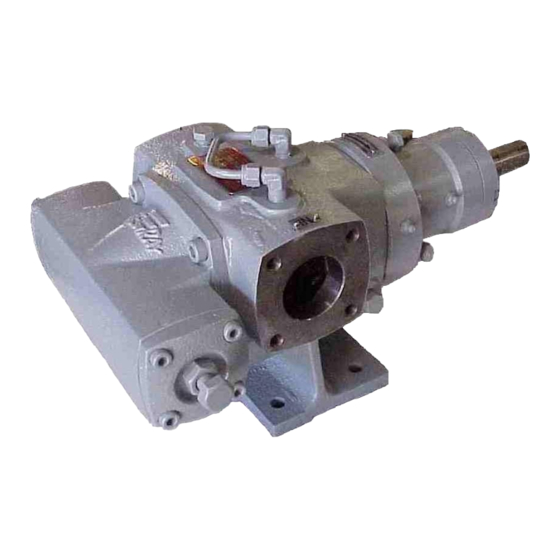
- Page 1 Publication # 2080-04 EBSRAY PUMPS INSTALLATION, OPERATION & MAINTENANCE INSTRUCTIONS E SERIES MODEL E20HD...
-
Page 2: Section 1 - General
Should any change be contemplated, please confer with EBSRAY in order to verify the suitability of such a change. SECTION 2 – INSTALLATION 2.1 LOCATION 2.2 FOUNDATIONS The pumping unit should be placed as close... -
Page 3: Pump Piping Connections
2.3 PUMP PIPING CONNECTIONS All piping should be supported independently of and line up accurately with the pump ports. SEVERE DAMAGE COULD RESULT IF PIPING IS DRAWN INTO PLACE BY USE OF FORCE AT THE PORT CONNECTIONS OF THE PUMP. 2.4 STRAINER PROTECTION Figure 3 The pump suction should always be protected... -
Page 4: Section 3 - Operation
SECTION 3 - OPERATION pressures when compared with conventional 3.1 DESCRIPTION The EBSRAY internal gear principle is based gear pumps, many of which employ costly upon the use of an outer rotor 'A', idler gear, external timing gears to minimise tooth wear. -
Page 5: Spare Parts
3.7 VALVE Some configurations of EBSRAY's Model The valve can be configured upon assembly E20HD pump incorporate an integral valve, for either CW or CCW rotation. which is fully adjustable. This feature, when fitted protects the pump from excessive On commissioning, the bypass valve if fitted... -
Page 6: Reassembly- Preliminary
EBSRAY recommend replacement of the pump. all gaskets, seals and 'O' Rings at every overhaul, to ensure positive sealing. - Page 7 Table of Clearances Refer to diagram below - All clearances in millimetres Running Clearances STANDARD Radial - Outer Rotor to Body 0.038 - 0.071 Axial - Rotors to Cover 0.05 Diametral - Rotor Pin to Bearing 0.038 - 0.063 Radial - Inner Rotor to Crescent 0.025 - 0.050 Figure 6 4.6 REASSEMBLY...
- Page 8 Pack pump end bearing fully with Loosen bearing carrier capscrews and grease and press fit the bearing over slowly tighten adjustment screws until shaft end into bearing carrier until rotor is pulled back in body. Assemble inner cone is fully seated against inner rotor over inner rotor pin and fit shaft shoulder.
-
Page 9: Section 5 - Trouble Shooting
Bypass Valve Assembly: Note: For correct orientation of bypass valve Fit 'O' Ring to adjusting cover and fit - adjusting screw should be on the retaining washer. same side of the pump as the suction port as determined by rotation and Position spring on retaining washer direction of flow. -
Page 10: Excessive Power Consumption
Removing suction line restrictions positions when the pump is installed. created by: Inadequate pipe sizes excessive line lengths. EBSRAY PUMPS PTY. LTD. 628 Pittwater Rd Brookvale NSW 2100 AUSTRALIA Phone: (+61 2) 9905 0234 Fax: (+61 2) 9938 3825... -
Page 11: Section 6 - Parts Designation
SECTION 6 - PARTS DESIGNATION E20HD Parts - Refer To drawing No: A300001H CAT # DESCRIPTION BODY COVER 'O' RING CAP SCREW SEAL FACE (rotating) SEAL SEAT (stationary) SPRING-SEAL DRIVE PIN SEAL SLEEVE GRUBSCREW 'O' RING 'O' RING 'O' RING ADAPTOR PLATE 'O' RING ROTOR/SHAFT ASSEMBLY...
Need help?
Do you have a question about the E Series and is the answer not in the manual?
Questions and answers