
Related Manuals for Servomex SERVOPRO k2001


Summary of Contents for Servomex SERVOPRO k2001
- Page 1 SERVOPRO Plasma (k2001) Trace N Analyser User Manual Part Number: 02001001A Revision: Language: UK English...
- Page 2 This page intentionally blank...
-
Page 3: Table Of Contents
TABLE OF CONTENTS 1.0 CONCERNING THIS MANUAL.......................... 2 2.0 CAUTIONS AND WARNINGS ..........................3 Symbols description........................... 3 Caution ..............................3 Electrical shock hazard ..........................3 Possible explosion hazard.......................... 3 General precautions for handling and storing high pressure cylinders............5 Gas hazard ..............................5 General safety instructions......................... - Page 4 User Manual SERVOPRO Plasma Trace N Analyser APPENDIX 4 / RS-232C ............................70 APPENDIX 5 / WEEE ..............................74 Product disposal in accordance with the Waste Electrical and Electronic Equipment (WEEE) Directive 2002/96/EC75 APPENDIX 6 / APPLICATION NOTES ........................76 SAMPLING LINE SIZE, (AN-01)..........................
-
Page 5: Concerning This Manual
The reader should contact Servomex if errors are suspected. In no event shall Servomex be liable for any damages arising out of or related to this document or the information contained in it. -
Page 6: Cautions And Warnings
User Manual SERVOPRO Plasma Trace N Analyzer 2.0 CAUTIONS AND WARNINGS Symbols description Caution Improper installation, operation or service of this analyzer may cause damage to the analyzer and void the manufacturer’s warranty. Electrical shock hazard Do not operate unless the cabinet is securely closed. Servicing this instrument implies possible exposure to shock hazard level voltages which can cause death or serious injury. - Page 7 User Manual SERVOPRO Plasma Trace N Analyzer This analyzer must be installed in laboratory environments: moisture- and vibration-free, with stable temperatures. 2.0 CAUTIONS AND WARNINGS...
-
Page 8: General Precautions For Handling And Storing High Pressure Cylinders
User Manual SERVOPRO Plasma Trace N Analyzer General precautions for handling and storing high pressure cylinders This analyzer is frequently applied to verify the contents of high-pressure cylinder gases. Mishandling of gas cylinders could result in death, serious injury or property damages. Handle gas cylinders with extreme care. -
Page 9: General Safety Instructions
User Manual SERVOPRO Plasma Trace N Analyzer The nitrogen is a diatomic molecule and is colorless, odorless and non toxic. However, nitrogen can also act as a simple asphyxiate by displacing the necessary amount of oxygen to support life. Proper ventilation must be done to provide safe area. General safety instructions To avoid the risk of electric shock, do not remove the casing or open the back. - Page 10 Servomex reserves the right to interrupt all business relationship and warranty or service if there is any tentative from any customers to reverse engineering any of Servomex products or to tamper with any sealed module.
-
Page 11: Specifications
User Manual SERVOPRO Plasma Trace N Analyzer 4.0 SPECIFICATIONS Plasma Emission Detector (PED). Detector type: Material: Quartz, single element, vacuum tight to 69 kPa (10 Psig) Range: 0 – 1 ppm display resolution to 10 ppb X10: 0 – 10 ppm display resolution to .1 ppm X100: 0 –... - Page 12 User Manual SERVOPRO Plasma Trace N Analyzer • Fully microprocessor-controlled, with 4 x 40 LCD display • Self-diagnostic system software • Auto-zero, auto-span calibration system (optional). Provides maintenance-free system • Digital output: 4 digital outputs: 3 are for range indication and1 for system status monitoring Relay contact rating: 30 Vrms, 42.4 V peak or 60 Vdc •...
-
Page 13: Description
User Manual SERVOPRO Plasma Trace N Analyzer 5.0 DESCRIPTION General description The SERVOPRO PLASMA Trace Nitrogen in argon Analyzer is an instrument for measuring 0 to 100 ppm nitrogen in argon. This analyzer is designed to work with pure gas. Avoid introduction of air into the sampling system. - Page 14 User Manual SERVOPRO Plasma Trace N Analyzer 5.0 DESCRIPTION...
-
Page 15: Analysis Section
User Manual SERVOPRO Plasma Trace N Analyzer Analysis section The sample gas, which at atmospheric pressure, flows through a proprietary design; a pure quartz cell is submitted to a high-frequency, high-intensity electromagnetic field. The SERVOPRO PLASMA Analyzer is based on a spectroscopic emission cell, which in itself is not a new technique. -
Page 16: Electronics
User Manual SERVOPRO Plasma Trace N Analyzer The resulting light is directed to a special photodiode, where an electrical current is generated. This current is proportional to the nitrogen level in the argon stream. By regulating the power of the plasma and having close control of plasma position with the focusing electrodes;... -
Page 17: Description Of Controls And I/O Ports
User Manual SERVOPRO Plasma Trace N Analyzer 5.6 Description of controls and I/O ports Description Keypad LCD display Power inlet Gas connections Ethernet port RS-232 port IO Connector 5.0 DESCRIPTION... -
Page 18: Installation
User Manual SERVOPRO Plasma Trace N Analyzer 6.0 INSTALLATION Electrical Connect the line cord to the proper line voltage according to the model you have (i.e. Voltage: 100 to 120 Vac or 220 to 240 Vac; Frequency: 50 to 60 Hz). For optimum unit performance this voltage must be stable, transient-free and have a stable frequency. -
Page 19: Analyzer Cabinet Installation
User Manual SERVOPRO Plasma Trace N Analyzer Regulator purging is critical. When you connect the regulator to a cylinder, it is full of air (790 000 ppm of N ). If you open the valve on the cylinder and leave it open even for a short period of time, the air inside the regulator will diffuse into the cylinder. - Page 20 User Manual SERVOPRO Plasma Trace N Analyzer 1. TO AVOID DAMAGE TO ANALYZER, ALWAYS LEAVE THE PROTECTION CAPS ON GAS CONNECTIONS UNTIL CLEAN GAS IS READY TO FLOW IN THE ANALYSER. 2. THE VENT CONNECTION OF THE ANALYZER MUST BE AT ATMOSPHERIC PRESSURE ALL THE TIME.
- Page 21 User Manual SERVOPRO Plasma Trace N Analyzer ANALYZER FRONT END SYSTEM SERVOPR PR1 is a miniature stainless steel high purity pressure regulator. The internal volume must absolutely be at it’s minimum. Any unswept dead volume will cause noise and instability and, will cause poor recovery time. PR1 should be installed close to the sample point.
- Page 22 User Manual SERVOPRO Plasma Trace N Analyzer ANALYZER FRONT END SYSTEM SERVOPR Some users wish to monitor the inlet pressure. Connecting a pressure gauge at the inlet will result in big unswept volume. This will cause poor response time, drift and noise. DON’T DO THIS! Problems caused: - long response time - will eventually read below the scale because of error of calibration.
- Page 23 User Manual SERVOPRO Plasma Trace N Analyzer ANALYZER FRONT END SYSTEM SERVOPR Some users wish to monitor the inlet flow with a falling ball rotometer. Those rotometers (or flowmeters) are calibrated at atmospheric pressure. The flow indicated will be wrong, it must be compensated for the line pressure.
- Page 24 User Manual SERVOPRO Plasma Trace N Analyzer ANALYZER FRONT END SYSTEM SERVOPR Some users wish to avoid back flow from a vent header into the analyzer vent. Doing so will cause sample flow and cell pressure variation. The cell pressure will follow header pressure variation. Check valve cracking pressure is not constant.
- Page 25 User Manual SERVOPRO Plasma Trace N Analyzer SAMPLE STREAM SELECTION SYSTEM ACCEPTABLE All V valves are diaphragm or bellow type valves made of stainless steel. The connections are ⅛”double ferrule compression type. The inlet by-pass rotometer could be installed to provide faster response time. By-pass flow must be constant.
- Page 26 User Manual SERVOPRO Plasma Trace N Analyzer SAMPLE STREAM SELECTION SYSTEM BETTER The loop eliminates the problem introduced by the length of section . Here only dead volume introduced by section is present. By making these lengths as small as possible, the problem still is tolerable. 6.0 INSTALLATION...
- Page 27 User Manual SERVOPRO Plasma Trace N Analyzer 6.0 INSTALLATION...
- Page 28 User Manual SERVOPRO Plasma Trace N Analyzer 6.0 INSTALLATION...
-
Page 29: Operation
User Manual SERVOPRO Plasma Trace N Analyzer 7.0 OPERATION All analyzer functions are controlled through different menu options. The following figures in this section show the overall menu structure. You must become familiar with it. At power on, the analyzer displays the MAIN MENU. KONTROL ANALYTIK K2001 TRACE N2 ANALYZER MAIN MENU F1:Configuration... -
Page 30: Calibration
User Manual SERVOPRO Plasma Trace N Analyzer 3. Analog output mode: by pressing the "F2" key, the analog 4 - 20 mA output will be in either "track" or "hold" mode. Hold mode: "hold" will maintain analog output at last "on run" gas value when exiting run mode. - Page 31 User Manual SERVOPRO Plasma Trace N Analyzer From MAIN MENU, when you press the F2 key, the CALIBRATION MAIN MENU is displayed on the analyzer. See Fig. 4. <<CALIBRATION MENU>> F1:Zero F2:Span F3:Calibrate F4:RET FIGURE 4: MAIN CALIBRATION You enter your zero calibration gas value in ppm, as well as your span calibration gas value. This is done by selecting F1 for the zero value, and F2 for the span value.
-
Page 32: Important Facts Concerning Calibration
User Manual SERVOPRO Plasma Trace N Analyzer The following figure shows this sub-menu: <<CALIBRATION FACTORS CALCULATION>> Measure: 9 Sample Flow: 25 F1:Zero F2:Span F4:RET Calibration status: FIGURE 7: CALIBRATION SUB MENU The display shows the actual ppm of nitrogen value and the actual flow in cc. If the unit is started up for the first time or you replace the calibration gas with a new value, the ppm display has no meaning. -
Page 33: Diagnosis
User Manual SERVOPRO Plasma Trace N Analyzer the use of a getter to generate the zero gas and a span gas having 7 to 9 ppm for calibration if the 0-1 and 0-10 ppm ranges are the most frequently used. There is no offset between ranges with the SERVOPRO PLASMA;... - Page 34 User Manual SERVOPRO Plasma Trace N Analyzer If you have any options other than standard, you may also verify them (digital and/or fully automatic calibration option). Please refer to the appropriate appendix of this manual. <<DIAGNOSTIC MENU>> F3:NEXT Cell counts: 13120 Flow counts: 1666432 Temperature: 24.45 F2:Error and Alarm historic...
-
Page 35: Error And Alarm Historic
User Manual SERVOPRO Plasma Trace N Analyzer remote monitoring system and also makes it faster to verify the hardware part for the 4 - 20 mA signal isolation module. NOTE: the analog output mode selected from the configuration menu ("track" or "hold") will affect the 4 - 20 mA output. -
Page 36: Ethernet Info
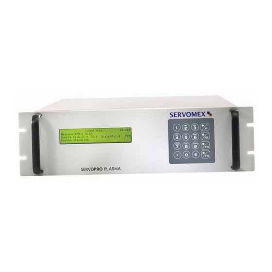
The MAC address can’t be changed. It is a hardware characteristic set by Servomex. But to configure the mask, the gateway or change the Ethernet password, go to the Ethernet pages of the HIDDEN MENU. Refer to the WEB INTERFACE section for a connectivity procedure. - Page 37 User Manual SERVOPRO Plasma Trace N Analyzer <<RUN MODE>> F4:RET Measure(PPM): 10.0 Sample flow(CC): 75.0 Scale: 0-10 PPM System status:OK FIGURE 14: RUN MODE In this mode, the following information is displayed: measurement in ppm, flow in cc, system status, and range in use. The 4 - 20 mA output is refreshed to reflect the level of impurities according to the scale in use.
-
Page 38: Special Consideration About The 0 - 1 Ppm Range
User Manual SERVOPRO Plasma Trace N Analyzer Other messages can appear depending on options or custom features ordered (auto-zero, auto- span). When an error is detected, the status (ST) digital output will be deactivated (contact open). NOTICE: When the flow is lower than 20 cc for longer than 30 seconds, an internal relay will shut down the plasma generator and the appropriate message will be displayed. -
Page 39: Temperature Coefficient
There is a procedure to follow to do temperature tests. If you have to do it, call Servomex to get the exact procedure. It must be done by trained personnel. Most of the time there is no compensation and these factors are then set to 1.000. - Page 40 User Manual SERVOPRO Plasma Trace N Analyzer If you have to change the offset compensation factor, enter the value with the numeric keypad and then, press E to validate the new value. Press F2 to access the temperature gain menu. <<<TEMPERATURE GAIN>>>...
-
Page 41: Time And Date Setting
User Manual SERVOPRO Plasma Trace N Analyzer 7.6.3 Time and date setting When you enter in the time and date setting menu, the following menu appears. Enter time first, using the numbers on the keypad. For example, if you wish to enter 15:45:02, you only have to do the following steps. -
Page 42: System Gain
User Manual SERVOPRO Plasma Trace N Analyzer <<<TIME AND DATE SETTING>>> Time HH:MM:SS Actual: 15:46:23 Date YY/MM/DD Actual: 05/06/27 F3:NEXT F4:RET FIGURE 21: TIME AND DATE SETTING If you enter a bad value, the analyzer clears the field and you are asked to enter a new one. 7.6.4 System Gain This value is used to adjust the last stage of amplification. -
Page 43: Pid Values
User Manual SERVOPRO Plasma Trace N Analyzer 7.6.5 PID values <<<PID values>>> 1-Proportional 2- Integral 3-Derivative Sample flow(CC):25.0 F3:NEXT F4:RET FIGURE 23: GAS FLOW PID VALUES The PID values are the proportional, integral and derivative constant of the loop controlling the gas flow. -
Page 44: Ethernet Configuration 1
User Manual SERVOPRO Plasma Trace N Analyzer If the lock range is set ‘’OFF’’, the user is allowed to manually change the range in the run menu. If it is set ‘’ON’’ the range cannot be changed. NOTE: To lock the range, you must disable the auto ranging in the configuration menu. NOTE: You cannot activate the auto ranging if the range is locked. -
Page 45: Ethernet Configuration 2
User Manual SERVOPRO Plasma Trace N Analyzer 7.6.8 Ethernet configuration 2 Press F3 from the first page of the Ethernet configuration 1 menu to access the second page. <<<ETHERNET CONFIGURATION 2>>> F1:DHCP Enabled?(Yes/No):Yes F3:NEXT F4:RET FIGURE 28: ETHERNET CONFIGURATION 2 PAGE with DCHP on If the analyzer is connected to the Internet via a DHCP server, the network router assigns a TCP/IP address automatically to the analyzer. -
Page 46: Averaging Number
User Manual SERVOPRO Plasma Trace N Analyzer Contact your network administrator to set-up this aspect of the analyzer. You must first know the Gateway of your network. Set it by pressing F3. Then, enter a value of 1 to 3 digits and press E (enter). -
Page 47: Calibration Done Parameters
User Manual SERVOPRO Plasma Trace N Analyzer 7.6.10 Calibration done parameters <<<CALIBRATION DONE PARAMETERS>>> Slope (x10K): 0.0000 Offset: 0.000 Zero: 0 Span: 0 F4:RET FIGURE 32: CALIBRATION DONE PARAMETERS This menu displays the calibration values calculated by the analyzer. In front of “Zero”, we find the analog to digital converter counts of the signal measured with the zero gas. - Page 48 User Manual SERVOPRO Plasma Trace N Analyzer STEP 3, the router: the analyzer now acts as a server over the network. If you want to access it from outside the local network, the network router must allow the IP address to be accessed from the Internet on TCP port 3076.
- Page 49 User Manual SERVOPRO Plasma Trace N Analyzer STEP 5, the browser: the last step before being able to completely control the analyzer through a network is to type in the password that you can see and change in the Ethernet Configuration 1 page of the HIDDEN MENU and to click on the Submit button.
- Page 50 When necessary, this second network can be connected to the first one in order to be accessed from the Internet, by Servomex Canada support team for example. NOTE: the SERVOPRO PLASMA web interface has been tested on a computer equipped with Internet Explorer 5.5 to 6.0 on Windows XP with Service Pack 1, with no Antivirus software and...
- Page 51 User Manual SERVOPRO Plasma Trace N Analyzer First try to turn off the “Windows Firewall”. Go in the “Control Panel”, click on the “Network Connections”, right-click on your “Local Area Connection” and select “Properties”. Then, select the “Advanced” tab. Click on “Settings” and select “Off” as the Windows Firewall option.
-
Page 52: Start-Up
User Manual SERVOPRO Plasma Trace N Analyzer 8.0 START-UP Once all lines are purged and cleaned, put the power "ON" with the switch at the rear of the analyzer. The display will come on and show the MAIN MENU. When the system is powered up, the flow set point has a default value of 75 cc; it normally does not require further setting, except for faster purging. -
Page 53: Routine And Operational Verification
User Manual SERVOPRO Plasma Trace N Analyzer Routine and operational verification From time to time, it is a good idea to go in the "DIAGNOSTIC MENU", check cell counts with a reference gas and record this value for comparison with a later value. This gives an indication of the degree of cell offset. - Page 54 It is a good idea to find out how this analysis was done. Servomex is a good customer of such cylinders coming from different sources of specialty gases. Sometimes, with three cylinders containing the same quantity of impurities (less than .2 ppm total difference), each coming from different suppliers, we obtained some surprising readings.
-
Page 55: Maintenance And Trouble Shooting
User Manual SERVOPRO Plasma Trace N Analyzer 9.0 MAINTENANCE AND TROUBLE SHOOTING Maintenance This analyzer is maintenance-free. You only need to calibrate at the frequency determined by your experience. Normally, if you use a clean gas and a good sampling system, a calibration every two weeks is enough. -
Page 56: Problem Causes
User Manual SERVOPRO Plasma Trace N Analyzer Problem causes PROBLEM POSSIBLE CAUSE REMEDY Power is on but display is Fuses, or power cord Connect power cord or • • still off not connected replace fuse Display is off, fuses are DC power supply Replace each module •... -
Page 57: Appendix 1 / Hardware And Technique
User Manual SERVOPRO PLASMA Trace N2 Analyzer APPENDIX 1 / HARDWARE AND TECHNIQUE APPENDIX 1... - Page 58 By Servomex, Québec, Canada. Introduction Servomex produces very sensitive equipment for low level measurements in the range of ppm and ppb. In such types of measurements, the stability, accuracy and response time of the system are greatly dependent on the gas sampling lines, regulators, valves and cylinders in use; operator manipulations are also crucial, one must be careful .
- Page 59 For all your gas lines and pressure regulators, stream selection valves and fittings, use stainless steel. The use of pipe thread fittings is not recommended by Servomex, and the performance of the analyzer is not guaranteed under this condition of use.
- Page 60 User Manual SERVOPRO PLASMA Trace N Analyzer The following table gives some permeation factors of the most commonly used so-called "plastic tubing". PERMEABILITY (approx.) AT 25 TUBING PERMEABILITY (approx.) − FORMULATION cc mm − Units : −...
- Page 61 The only type of trap that we recommend is the T-3A-R available from Servomex. Almost all of commercially available traps use molecular sieves with 5A or 13X. The use of such traps will introduce a lot of drift and a long response time.
- Page 62 User Manual SERVOPRO PLASMA Trace N Analyzer APPENDIX 1...
- Page 63 User Manual SERVOPRO PLASMA Trace N Analyzer Regulator purging Regulator purging is an operation that is not always given the attention it deserves in the use of both high-purity gases and calibration gases. It is easy to understand that special precautions are necessary when using theses types of gases.
- Page 64 3. Avoid the use of rotary stream selection valves. If you have no choice, use a valve with the smaller orifice available to avoid cross flow port contamination; furthermore, install on particle filter on each inlet port. However, please remember that this is not recommended by Servomex Canada. APPENDIX 1...
- Page 65 User Manual SERVOPRO PLASMA Trace N Analyzer 4. If you are installing a SERVOMEX ppb analyzer, all compression tube fittings must be ® replaced with metal-to-metal seal fittings, (so called VCR -type fittings). Tubing size will be 1/4" electropolished stainless steel. All accessories (i.e. sample trap, valves, filters) must have ®...
-
Page 66: Appendix 2 / Analogue And Digital Outputs
User Manual SERVOPRO PLASMA Trace N2 Analyzer APPENDIX 2 / ANALOGUE AND DIGITAL OUTPUTS APPENDIX 2... - Page 67 User Manual SERVOPRO PLASMA Trace N Analyzer DIGITAL OUTPUT / ALARM OUTPUT OPTION The digital output permits the transmission of the range in use and, also, the transmission of the analyzer status (internal alarms). This is done by using four (4) dry contact outputs, labeled S1, S2, S3, ST. S1 is for 0-1 ppm, S2 is for 0-10 ppm and S3 for 0-100 ppm.
- Page 68 User Manual SERVOPRO PLASMA Trace N Analyzer ALARM OUTPUT OPTION With this option, two digital dry contact outputs are available for process alarms. These contacts are always closed for fail safe purposes. They are connected to a terminal strip labeled "AL1" for alarm #1 and "AL2"...
- Page 69 User Manual SERVOPRO PLASMA Trace N Analyzer To enter the set point for alarm #2, follow the same procedure as above, but press F3, this will bring up the following display. <<CONFIGURATION MENU>> Page 2 F1:mA failure mode (High/Low/Off): HIGH F2:Alarm #1 Set Point:95.0 Input Alarm#2:99.0 Actual:100.0...
- Page 70 User Manual SERVOPRO PLASMA Trace N Analyzer 30 Vrms, 42.4 V peak, 60 Vdc, 1 A max. APPENDIX 2...
- Page 71 User Manual SERVOPRO PLASMA Trace N2 Analyzer External connections WARNING The milliamp output, and Ethernet and RS-232 terminals (where fitted) are separated from the analyzer mains circuits by reinforced insulation. The terminals must only be connected to circuits that are themselves separated from mains voltages by at least reinforced insulation. Circuits connected to terminals S1, S2, S3, ST, AL1 and AL2 shall only be powered by supply connected to terminal C.
- Page 72 User Manual SERVOPRO PLASMA Trace N Analyzer WARNING The cable connected to the mA output terminal shall not be longer than 30 m, nor shall it leave the building in which the analyzer is installed without suitable isolation, nor shall it be routed outside of the building in which the analyzer is installed.
-
Page 73: Appendix 4 / Rs-232C
User Manual SERVOPRO PLASMA Trace N Analyzer APPENDIX 4 / RS-232C APPENDIX 2... - Page 74 User Manual SERVOPRO PLASMA Trace N Analyzer RS-232C SERIAL COMMUNICATION OPTION Introduction With this option installed, this analyzer retransmits the operating parameters and process values to a remote computer through a serial link. The computer is connected to the analyzer by the mean of a DB-9 RS-232C (Null-modem) cable.
- Page 75 User Manual SERVOPRO PLASMA Trace N Analyzer • Baud rate: 9600 • Parity bits: none • Data bits: • Stop bits: 1.2. Transmission protocol The different parameters are transmitted in the following order: ppm value sign, ppm value, TAB, flow, TAB, flow counts, TAB, cell counts TAB, status and range, TAB, checksum, CR.
- Page 76 User Manual SERVOPRO PLASMA Trace N Analyzer The data sent in ASCII is: Data Check sum “+”, “NUL”, “4”, “0”, “.”, “1”, “0”, “TAB”, “NUL”, “7”, “5”, “.”, “0”, “0”, “TAB”, “NUL”, “8”, “3”, “8”, “8”, “6”, “0”, “0”, “TAB”, “NUL”, “NUL”, “1”, “9”, “0”, “0”, “1”, “1”, “TAB”, “)”,...
-
Page 77: Appendix 5 / Weee
User Manual SERVOPRO PLASMA Trace N2 Analyzer APPENDIX 5 / WEEE... -
Page 78: Product Disposal In Accordance With The Waste Electrical And Electronic Equipment (Weee) Directive 2002/96/Ec75
For additional information and advice on the disposal of the analyser in accordance with the requirements of the WEEE Directive, contact Servomex at info@servomex.com or your local Servomex agent. • If you send the analyser to Servomex or your local Servomex agent for disposal, the analyser must be accompanied by a correctly completed decontamination certificate. APPENDIX 5... -
Page 79: Appendix 6 / Application Notes
User Manual SERVOPRO PLASMA Trace N Analyzer APPENDIX 6 / APPLICATION NOTES APPENDIX 6... -
Page 80: Sampling Line Size, (An-01)
(for silent electric discharge type) or 1.48 cubic inlet. This can lead to long lag time limiting the feet (700 sccm) for ion mobility type. Servomex speed of response of an analytical system. For Canada analyzer works with a default sample example, sample line of 100 feet of ¼"... - Page 81 User Manual SERVOPRO PLASMA Trace N Analyzer APPENDIX 6...
-
Page 82: The Importance Of Regulator Purging, (An-01)
User Manual SERVOPRO PLASMA Trace N Analyzer THE IMPORTANCE OF REGULATOR PURGING, (AN-01 Here are some quick calculations to help you understand why it is so important to have some techniques to evacuate the air from pressure regulators when replacing calibration cylinders. For example, let’s take a pure argon cylinder of size 44 (i.e. -
Page 83: Leak Finding Procedure (An-05)
User Manual SERVOPRO PLASMA Trace N Analyzer LEAK FINDING PROCEDURE (AN-05) Experience has shown that bad analysis results often come from inboard contamination following from leaks in the tubing bringing the sample to the analyzer’s detector. Using the right procedure, the trace Nitrogen analyzer SERVOPRO PLASMA can self diagnose the presence or absence of contaminating leaks. - Page 84 Anyway, these possible problems have been checked and solved at Servomex Canada factory (regarding the analyzer itself). So a properly installed fitting, when tightened, is preloaded i.e. there is a permanent pressure applied on the front ferrule against its seat providing therefore a good sealing.
- Page 85 The only important point is to know how to check if leaks are present and how to solve the problem. P.S.: Servomex also manufactures a patented sampling system using a principle that eliminates almost 100 % of the leaks inside it.
- Page 86 User Manual SERVOPRO PLASMA Trace N Analyzer LEAK FINDING TEST COMPANY NAME: __________________________TEL:____________________ CONTACT PERSON:_________________________FAX:____________________ ANALYZER’S SERIAL NUMBER: _____________E-MAIL:_________________ APPROXIMATE TIME ELAPSED SINCE START-UP: _____________________ ZONE 1 TEST WE SUGGEST TO USE THE ZERO CALIBRATION GAS TO RUN THE TEST PPM VALUE OF THE GAS BEING USED: _____ ppm PRESSURE READ FLOW DISPLAYED...
- Page 87 User Manual SERVOPRO PLASMA Trace N Analyzer ZONE 1 - TEST WITH SPAN GAS PPM VALUE OF THE GAS BEING USED: _____ ppm PRESSURE READ FLOW DISPLAYED PPM DISPLAYED CELL COUNTS ON REGULATOR BY ANALYZER NORMAL PRESSURE PRESSURE ZONE 2 - TEST WITH SPAN GAS PPM VALUE OF THE GAS BEING USED: _____ ppm PRESSURE READ FLOW DISPLAYED...
-
Page 88: Appendix 7 / Auto-Calibration Option
User Manual SERVOPRO PLASMA Trace N Analyzer APPENDIX 7 / AUTO-CALIBRATION OPTION APPENDIX 7... -
Page 89: Automatic Calibration Option
User Manual SERVOPRO PLASMA Trace N Analyzer AUTOMATIC CALIBRATION OPTION NOTE TO THE READER: Before proceeding with this section you must first have read and understood the User Manual. Furthermore the analyzer must be properly started-up. Good calibration depends on hardware used in sampling system. 1) Gas Circuit Description Analyzers with this option are equipped with 3 solenoid valves. -
Page 90: Entering Zero And Span Gas Values
User Manual SERVOPRO PLASMA Trace N Analyzer 2.1 Entering Zero and span gas values From the main menu, press F2 to enter the calibration menus of the analyzer. SERVOPRO CHROMA KONTROL ANALYTIK TRACE N2 ANALYZER MAIN MENU F1: Configuration F3: Diagnostic F2: Calibration F4: Run FIG 1: ANALYZER MAIN MENU... -
Page 91: Manual Calibration
User Manual SERVOPRO PLASMA Trace N Analyzer <<CALIBRATION MENU>> Input SPAN value: 0.00 Actual Value:0.00 Value must be in PPM F4:RET FIG 5: SETTING THE SPAN GAS VALUE With the numeric keys, enter the zero gas value in PPM followed by the E key. The actual value of the zero gas is then updated in front of “Actual value:”. -
Page 92: Automatic Calibration Mode
User Manual SERVOPRO PLASMA Trace N Analyzer <<CALIBRATION FACTOR CALCULATION>> Measure:0.00 PPM Sample Flow:75.0 RE-ZERO(F2-Yes F1-No) SPAN NOT SET Calibration status: FIG 7: CALIBRATION FACTOR CALCULATION MENU To re-span the instrument, a re-zero must have been performed before. You must then allow the span gas to flow in the analyzer. If your analyzer has the auto-calibration option, select “SPAN”... - Page 93 User Manual SERVOPRO PLASMA Trace N Analyzer To configure the analyzer to perform automatic calibrations, first set the different timers by going to the HIDDEN MENU. To access the HIDDEN MENU, go to the MAIN MENU and enter the secret code by pressing 1, 2, 3, and E consecutively on the keyboard.
- Page 94 User Manual SERVOPRO PLASMA Trace N Analyzer “ELAPSED TIME SINCE LAST CAL.” is the number of hours since the analyzer was put in automatic calibration mode. The value displayed next to “MINUTES ON CAL. GAS” is the number of minutes the analyzer has spent on calibration gas (zero or span) since the zero or span gas was selected.
- Page 95 User Manual SERVOPRO PLASMA Trace N Analyzer FIG 12: SERVOPRO PLASMA WITH AUTOMATIC CALIBRATION APPENDIX 7...
-
Page 96: Appendix 8 / Trace Nitrogen In Helium Version
User Manual SERVOPRO PLASMA Trace N Analyzer APPENDIX 8 / TRACE NITROGEN IN HELIUM VERSION APPENDIX 8... - Page 97 User Manual SERVOPRO PLASMA Trace N Analyzer User Manual This User Manual applies to both versions of SERVOPRO PLASMA analyzers, i.e. Argon or Helium. Since the most popular version is Argon, all published manuals refer to Argon as background gas. You have to replace the word Argon by Helium when you are reading this manual.
-
Page 98: Appendix 9 / Dual Background Analyzers
User Manual SERVOPRO PLASMA Trace N Analyzer APPENDIX 9 / DUAL BACKGROUND ANALYZERS APPENDIX 9... - Page 99 User Manual SERVOPRO PLASMA Trace N Analyzer NOTE TO THE READER The SERVOPRO PLASMA trace nitrogen in argon or helium analyzer version is shipped configured for argon. We strongly recommend you read the standard User Manual followed by this addendum. Reading this addendum supposes that you have read and understood the User Manual.
- Page 100 1, 2, 3, E. This will bring up the menu showed on fig. 2. SERVOMEX CANADA K2001 TRACE N ANALYZER MAIN MENU...
- Page 101 User Manual SERVOPRO PLASMA Trace N Analyzer BACKGROUND GAS SELECTION ACTUAL GAS : HELIUM Use F1 key for selection F3 : NEXT F4 : QUIT FIG. 3 BACKGROUND GAS SELECTION MENU This menu is used for display and selection of the background gas type. The background gas may be helium or argon. Using "F1"...
- Page 102 Install the trap only when all lines are purged. This trap must be installed to get good results when operating under helium. This trap can be shipped back to Servomex Canada for proper regeneration. We strongly recommend to keep one in stock.
-
Page 103: Appendix 10 Compliance And Standards Information
User Manual SERVOPRO PLASMA Trace N Analyzer APPENDIX 10 COMPLIANCE AND STANDARDS INFORMATION APPENDIX 10... - Page 104 User Manual SERVOPRO PLASMA Trace N Analyzer • The analyzer complies with the European Community "Electromagnetic Compatibility Directive": Emissions: Class B - Equipment suitable for use in domestic establishments and in establishments directly connected to a low voltage supply which supplies buildings for domestic purposes. Immunity: “Basic”...
Need help?
Do you have a question about the SERVOPRO k2001 and is the answer not in the manual?
Questions and answers