Table of Contents
Advertisement
Quick Links
Advertisement
Table of Contents

Related Manuals for Servomex NanoTrace DF-760E


Summary of Contents for Servomex NanoTrace DF-760E
- Page 1 NanoTrace Dual Moisture/Oxygen Analyzer DF-760E Instruction Manual...
- Page 2 Servomex Corporation. NanoTrace Moisture Analyzer is a trademark of Servomex Corporation. VCR is a registered trademark of the Cajon Company. DF-760E Operator Manual...
- Page 3 Your NanoTrace Moisture Analyzer has been designed, manufactured and is supported under ISO-9001 controls, thus helping to insure the highest possible standards of quality. Every analyzer that Servomex manufactures is tested and operated on a variety of gas concentrations to insure that it functions properly when you receive it.
- Page 5 Follow the procedure below to unpack your NanoTrace Dual Analyzer 1. Examine the condition of the packaging and its contents. If any damage is apparent, immediately notify the carrier and Servomex. Do not proceed with the installation. 2. Check the contents against the packing slip to make sure the shipment is complete.
- Page 6 Thank you for selecting the NanoTrace Dual Analyzer. Servomex designs, manufactures, exhaustively tests, and supports every analyzer under the tightest quality controls. You should expect every Servomex analyzer to arrive in perfect working order and, with good maintenance, provide years of trouble-free service.
-
Page 7: Table Of Contents
1 Table of Contents Table of Contents ..............3 Table of Figures ......................6 Cautions..................9 Symbols and Explanations ...................9 Important Warnings ....................10 Specifications ................. 17 Oxygen ........................17 Moisture ........................17 General ........................17 Installation, Start Up and Shut Down ........21 Analyzer Installation .................... - Page 8 Keypad ........................46 Menu Structure ......................46 Main Menu ........................ 46 Moisture Menu ......................47 7.5.1 Moisture Controls Menu ................47 7.5.2 Moisture Calibrate Menu ................49 7.5.3 Moisture Data History Routine ..............55 7.5.4 Moisture Data Downloader Routine ............57 7.5.5 View Moisture Logs Menu ................
- Page 9 Maintenance ......................125 9.3.1 Oxygen Calibration ..................125 9.3.2 Storage Conditions ..................126 9.3.3 Oxygen Sensor Maintenance ..............127 9.3.4 Procedure for Adding Replenishment Solution to the Oxygen Sensor ..127 9.3.5 Moisture Cell Maintenance ................ 128 9.3.6 Vacuum Pump Maintenance ............... 128 9.3.7 Gas Purifier Maintenance ................
-
Page 10: Table Of Figures
1.1 Table of Figures Figure 1: Overall View ............................ 20 Figure 2: Major Internal Components ......................21 Figure 3: Aspirator Installation ........................24 Figure 4: Rear Panel Gas Connections and Controls ..................26 Figure 5: AC Power Input..........................27 Figure 6: Data Display Screen ......................... 28 Figure 7: Block Diagram of Gas Flow Path .................... - Page 11 Figure 57: Pump Pressure Failure ........................70 Figure 58: Pump Capacity Test Log ......................... 71 Figure 59: Oxygen SubMenu ........................... 71 Figure 60: Oxygen Controls Menu ........................72 Figure 61: Oxygen Sensor Gas Valve Control Screen ..................73 Figure 62: Oxygen Sensor On/Off Control Screen ..................73 Figure 63: Oxygen Calibrate Menu ........................
- Page 12 Figure 115: Purifier Warning ......................... 105 Figure 116: Fan Failure Alarm ........................105 Figure 117: Gas Delivery..........................106 Figure 118: Gas Delivery System Status ....................... 106 Figure 119: Back Flow Prevention Warning ....................107 Figure 120: Re-established flow delay ......................107 Figure 121: Adjust Contrast...........................
-
Page 13: Cautions
2 Cautions 2.1 Symbols and Explanations The following symbols are used on the analyzer labels and throughout this manual. CAUTION CONSULT MANUAL - ATTENTION CONSULTER LE MANUEL This symbol alerts the user to the presence of hazardous conditions that may be dangerous to individuals or equipment. To maintain safety consult the manual when this symbol is marked on a label, and read sections of the manual marked with this symbol. -
Page 14: Important Warnings
Cet analyseur doit être utilisé de manière conforme à l'usage prévu et tel que stipulé dans ce manuel. Servomex ne peut pas être tenu responsable des dommages directs ou indirects résultant de l'installation ou du fonctionnement de l'analyseur si ceux-ci sont réalisés d'une manière qui n'est pas décrite dans ce... - Page 15 CAUTION: POWER CORD SAFETY ATTENTION : SÉCURITÉ DU CORDON D’ALIMENTATION The power cord provides the protective earth connection. Ensure that the power cord is plugged into a properly grounded outlet that conforms to national and local electrical codes. Avoid damaging the power cord. Do not bend it excessively, step on it, or place heavy objects on it.
- Page 16 CAUTION: CHECK AC OPERATING VOLTAGE ATTENTION : VÉRIFICATION DE LA TENSION CA The analyzer has been factory set to operate on either 110 or 220 VAC. Check the voltage setting marked near the AC inlet. The analyzer may be damaged if operated on a different voltage than marked. Changing the operating voltage requires the analyzer to be returned to the factory.
- Page 17 CAUTION: FOR INDOOR USE, ONLY ATTENTION : UTILISATION À L'INTÉRIEUR SEULEMENT The DF-760 is for indoor use only. It should not be located in an area where it will be subjected to particulate, condensed moisture, caustic atmosphere, temperature extremes, or operation outside of any limits listed in section 3, Specifications.
- Page 18 6) For many toxic gases a breathing air safety monitor can be purchased (from a safety products distributor) that will notify the user if an unsafe amount of the toxic gas is detected. Servomex cannot be responsible for direct or consequential damages that result from using the analyzer with these gases. DF-760E...
- Page 19 être acheté (chez un distributeur de produits de sécurité) afin d'informer l'utilisateur si une quantité dangereuse de gaz toxique est détectée. Servomex ne peut pas être tenu responsable des dommages directs ou indirects résultant de l'utilisation de l'analyseur avec ces gaz. Cautions...
- Page 20 CAUTION: OXYGEN SENSOR OVERPRESSURE ATTENTION : SURPRESSION DU CAPTEUR D'OXYGÈNE Over-pressurizing the oxygen sensor can result in permanent damage to the sensor. Limit the backpressure to the analyzer to ±1 psig (±0.07 barg). Be sure the downstream isolation valve (if so equipped) is open before gas flow is started.
-
Page 21: Specifications
3 Specifications 3.1 Oxygen Lowest Detection Level (LDL): 75 ppt @ Constant Conditions Resolution: Analytical (Smallest Detectable Change): 50 ppt Display: 10 ppt Accuracy: Greater of ±3% of reading or ±0.1 ppb @ Constant Conditions Speed of Response: Typically less than 20 seconds to reach 90 percent of a step change in either direction Upset Recovery Time: Typically less than 15 minutes from a high ppm upset to within 10 ppb of the previous stable reading. - Page 22 EMI Sensitivity: Tested to standards EN61000-3-3 and EN61326-1 Weight: 72 pounds (32.6 kg) Environmental: Altitude: 2000 meters (6500 feet), max Ambient Operating Temperature: 10° C to 40° C (50° F to 105° F) Humidity: 80 % humidity for temperatures up to 31°C, decreasing linearly to 50% relative humidity at 40°C Indoor Use Only Pollution Degree: 2...
- Page 23 Alarm Relays: Four non-latching, independently assignable to oxygen alarms or to oxygen calibration-in-process indicator and four non-latching, independently assignable to moisture alarms. SPDT contacts rated at 1 Amp @ 30 VDC resistive load. Fail safe action upon loss of power to alarm condition. Not designed to switch AC power.
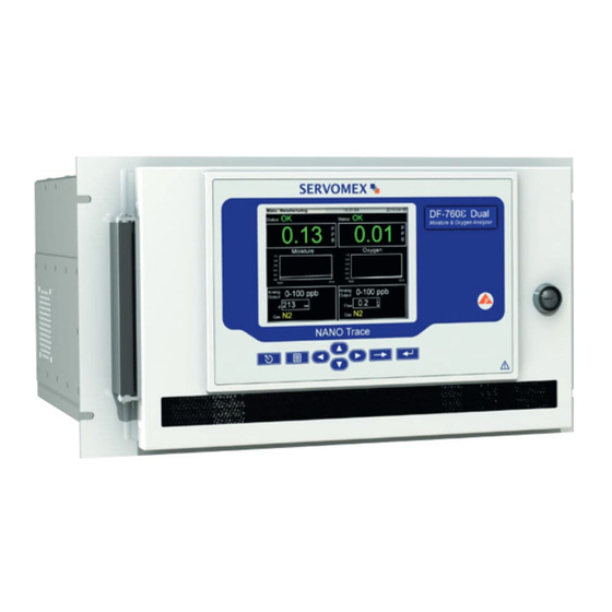
- Page 24 Figure 1: Overall View DF-760E Specifications...
-
Page 25: Installation, Start Up And Shut Down
4 Installation, Start Up and Shut Down The NanoTrace Dual analyzer is designed to measure the Moisture and Oxygen content of a sample gas simultaneously. This manual is written with the assumption that the user will be using the analyzer in this fashion. In addition, it may be operated to measure either Moisture or Oxygen. -
Page 26: Analyzer Installation
4.1 Analyzer Installation 4.1.1 General Warnings Read section 2.2 Important Warnings before installing this analyzer. DANGER The electrolyte is a caustic solution. Review the Material Safety Data Sheet (MSDS) before handling the electrolyte solution. NOTE The oxygen sensor is shipped dry and must be charged with electrolyte before it is operated. -
Page 27: Add Electrolyte To The Oxygen Sensor
2. Locate the oxygen sensor (see Figure 2) and remove the gold cap from the top. 3. Pour one full bottle (100 mL) of Servomex E-Lectrolyte Gold into the sensor. 4. Replace the cap securely on the top of the sensor. - Page 28 SAMPLE VENT ASPIRATOR 80 psi IN Figure 3: Aspirator Installation A regulated source of dry compressed gas (either N or air) is required at 80 psi (5.5 barg) and a flow rate of approximately 15 slpm. Connection is made to the aspirator by way of a ¼...
-
Page 29: Pneumatic Pressure Line Connection
4.1.6 Pneumatic Pressure Line Connection The pneumatic gas connection is a 1/8 inch compression fitting as shown in Figure 4 and requires 70 – 100 psig (4.8 - 6.9 barg) air or N2 pressure. For ease of installation, the pneumatic feed line can be connected directly to the ¼ inch aspirator source by way of a 1/8 inch adapter. -
Page 30: Electrical Connections
REGULATOR ADJUST PNEUMATIC GAS INLET RLY2-NC RLY4-NC RLY6-NC RLY8-NC RLY2-NO RLY4-NO RLY6-NO RLY8-NO RLY2-COM RLY4-COM RLY6-COM RLY8-COM RLY1-NC RLY3-NC RLY5-NC RLY1-NO RLY3-NO RLY7-NC RLY1-COM RLY5-NO RLY7-NO RLY3-COM RLY5-COM RLY7-COM AOUT+ AOUT- AOUT+ AOUT- 4-20mA+ 4-20mA+ 4-20mA- 4-20mA- BYPASS FLOW ADJUST PROCESS INLET MOISTURE SENSOR OUTLET OXYGEN SPAN INLET... -
Page 31: Hydrogen Service Safety System
CAUTION A 220 VAC power cord is not supplied with the analyzer. The customer supplied 220 VAC power cord should be rated for 250 VAC, 10 Amps and be equipped with an IEC 60320 C13 connector for connecting to the analyzer. This power cord provides the protective ground for the analyzer so it must have a protective earth wire. -
Page 32: Analyzer Start Up
Diagnostic Procedures while the various startup screens are displayed. Next, the Servomex logo is briefly displayed and then the data displays appear with the “Warming Up” screens flashing. The warm up process takes approximately six to nine minutes after which the display will look similar to Figure 6 (values shown are only representative). -
Page 33: Gas Delivery System
4.2.1 Gas Delivery System The gas delivery system as shown in Figure 7 is designed to deliver a gas flow rate of 1 liter per minute to both the moisture and oxygen sensor while maintaining the highest standards of gas purity and delivery for ultra-trace analysis. Features include a single inlet line for the gas sample, a bypass loop to maintain constant purging, and essentially dead- leg free delivery. -
Page 34: Moisture
6. The state of the gas control valves for each of the sensors is indicated on the main display. The default state of a factory-shipped instrument is isolation for both sensors. This can be adjusted in the Power Up Default section. If the sensors are in isolation, establish process flow via the Controls menu. -
Page 35: Oxygen
See the section on “Power Up Defaults on page 109 for setting user selectable preferences at the time of power up. 4.2.4 Oxygen Start the gas flow through the Oxygen Sensor by going to the Oxygen Controls Menu as shown on page 72 and select Gas Valves. On the Gas Valves screen Figure 61, highlight “Restore Process Gas Flow”... -
Page 36: Purifier Installation
The final step of the installation, after a couple days of dry down, should be to download the diagnostics (see section 7.7.11) and send them by e-mail to Servomex for review. This will allow the factory to confirm that the analyzer is working properly by comparison with data stored at the time of shipment, and in addition will set a baseline for comparison with future downloads, if any. - Page 37 MOISTURE SENSOR OUTLET REAR PANEL ASPIRATOR WITH BUILT IN VACUUM CONTROL NEEDLE VALVE MOISTURE SAMPLE VENT 80 psi IN TO CREATE VACUUM .010 ORIFICE REGULATOR ZERO ADJUSTMENT PURIFIER PROCESS INLET BYPASS FLOWMETER BYPASS FLOW ADJUST OXYGEN SPAN INLET FLOWSWITCH OXYGEN AND BYPASS OUTLET FLOW SENSOR Figure 7: Block Diagram of Gas Flow Path...
-
Page 39: Options
5 Options The following options to the DF-760 are available at the time of order: 5.1 Key Lock An optional key lock can be installed in the door of the analyzer to prevent access to the power switch and other internal components. The lock is supplied with two keys. If the analyzer is operating, the key lock does not prevent adjustments from the front panel. -
Page 40: Installation Of The Vacuum Pump
TO MOISTURE SENSOR OUTLET PLASTIC TUBING SUPPLIED POWER CORD TO VACUUM PUMP POWER CONNECTOR Figure 8: Vacuum Pump Assembly 5.6.1 Installation of the Vacuum Pump Mount the vacuum pump to the bracket Connect the line from the moisture sample outlet to the needle control valve and vacuum pump ... - Page 41 5.17 [131.32] 4.92 [124.97] 4.92 [124.97] Ø.28 [Ø7.14] 4 PL MOUNTING FOR 6.89 [175.01] 3.94 [100.08] BOTTOM OF BRACKET Ø.28 [Ø7.14] Ø.28[Ø7.14] 3.94 [100.08] 4 PL 4 PL 2 PL MOUNTING FOR LEFT OR MOUNTING FOR RIGHT SIDE OF BRACKET REAR OF BRACKET 3.94 [100.08] 2 PL...
-
Page 42: Moisture Sample Gas Outlet Connection To Vacuum Pump
5.6.2 Moisture Sample Gas Outlet Connection to Vacuum Pump The sample gas outlet connection is a ¼ inch compression fitting labeled Moisture Sensor Outlet as shown in Figure 4. Use the polyethylene tubing provided with the analyzer to connect between the outlet fitting and the ¼ inch fittings on the needle control valve and vacuum pump (included separately). - Page 43 REAR PANEL MOISTURE SENSOR OUTLET MOISTURE SAMPLE VENT EXTERNAL VACUUM PUMP (SUPPLIED LOOSE) VACUUM CONTROL NEEDLE VALVE (SUPPLIED LOOSE) .010 ORIFICE REGULATOR ZERO ADJUSTMENT PURIFIER PROCESS INLET BYPASS FLOWMETER BYPASS FLOW ADJUST OXYGEN SPAN INLET FLOWSWITCH OXYGEN AND BYPASS OUTLET FLOW SENSOR Figure 12: Block Diagram of Gas Flow Path with Optional Vacuum Pump...
-
Page 45: Connecting To External Devices
6 Connecting to External Devices The analyzer can be interfaced to a variety of external devices via the ports on the rear panel. Alarm contacts, voltage, and current outputs, and serial communications are supported. All outputs, analog or digital, are fully isolated from earth ground. NOTE During the six minute warm up period at startup, all analog and digital outputs are held to an artificial 0.011ppb reading to avoid the... -
Page 46: Analog Signal Outputs - J4, J10
See the chapter on Communications on page 113 for additional information on setting unit ID’s and baud rates. A program to facilitate serial communications is available from Delta F. Pin # Signal Description J5-8 Ground J5-7 4 wired 485 paired with TX+ J5-6 Unused J5-5... -
Page 47: Relay Ports - J2, J3, J8, J9
The maximum load resistance for each is 1K Ohms and the analyzer provides a compliance voltage of approximately 28 VDC for each. J4 Pin # Moisture Signal Description J4-8 Ground J4-7 J4-6 A Out + Analog Voltage Output (+) J4-5 A Out - Analog Voltage Output (-) J4-4... - Page 48 Pin # Moisture Relay Description J8-8 Ground J8-7 RLY2-NC Relay 2 Normally Closed J8-6 RLY2-NO Relay 2 Normally Open J8-5 RLY2-COM Relay 2 Common J8-4 RLY1-NC Relay 1 Normally Closed J8-3 RLY1-NO Relay 1 Normally Open J8-2 RLY1-COM Relay 1 Common J8-1 Unused J9-8...
-
Page 49: User Interface
7 User Interface 7.1 Data Display Screen The front panel display consists of the Graphical User Interface (GUI), as displayed on the view screen in Figure 14 below. Figure 14: Data Display Screen The left half of the front panel relates information from the moisture analyzer. The right half of the front panel relates information from the oxygen analyzer. -
Page 50: Keypad
The digital readout of the moisture or oxygen concentration will be over written with a warning if any of the level or system alarms are tripped. 7.2 Keypad The keypad allows the user to control all of the features of the Dual analyzer. The layout of the keypad on the front panel is represented in Figure 15. -
Page 51: Moisture Menu
keys ( ) to navigate up and down through the list. Select the highlighted item with the Enter key on the front panel. 7.5 Moisture Menu The Moisture SubMenu relates to the operation of the moisture cell without affecting oxygen sensor operation. Use the arrow keys ( ) to navigate up and down through the list. - Page 52 and hit the Enter key to begin the isolation process. The Isolate Sensor Warning will appear for 40 seconds. Figure 19: Isolate Sensor Warning While the moisture cell is isolated from gas flow, a warning will appear in the lower left corner of the main display indicating “Isolated”.
-
Page 53: Moisture Calibrate Menu
necessary for performing zero calibrations or for assessing the relative purity level of the incoming gas. See Figure 118 on page 106 for additional information on the various gas valves and their control. Figure 20: Moisture Gas Valve Control 7.5.2 Moisture Calibrate Menu Figure 21: Moisture Calibrate SubMenu “Calibration”... - Page 54 reference number during that time, or repeated restoration of the factory zero, will give the user a sense of the offset being induced by the user zero actions. 7.5.2.1 Check/Adjust Zero Figure 22: Moisture Check/Adjust Zero Screen The moisture Check/Adjust Zero screen displays many pieces of information including a live reading of moisture in ppb (or ppm) and the state of the zero gas control valves.
- Page 55 offset box will appear on the screen as shown in Figure 23. With the left and right arrow keys move the cursor to the right of the digit you want to change. With the up and down arrow keys set the number to the desired value. Figure 23: Moisture User Zero Offset Screen When done hit the Enter key which will move the highlighted area to the Apply button and hit Enter to set the value.
- Page 56 7.5.2.1.3 Do A Manual Zero Figure 25: Moisture Manual Zero Screen The manual zero command enables the user to zero the moisture cell in an interactive manner. For this purpose, it is necessary to ensure that moisture free gas is entering the sensor. This can be accomplished by opening the zero gas valves for the moisture cell.
- Page 57 Figure 26: Moisture AutoZero Screen NOTE: If oxygen is included in the background gas calculation, see page 103, the on- board zero gas purifier is automatically prevented from being used. As a result an adjustment of the moisture zero, must be done manually and the zero gas must be supplied from the outside through the sample inlet.
- Page 58 7.5.2.3 AutoZero Setup to Use the Next key to move from between fields and use the arrow keys ( change the highlighted selections and to enter numerical values. When done, use the Next key to move to the Accept button and hit the Enter key to return to the main display. Using the ESC key at anytime will exit the screen making no changes and return to the main display.
-
Page 59: Moisture Data History Routine
time, the AutoZero is automatically aborted and the Fail Zero flag is set in the Zero Cal Log as shown in Figure 38. The system provides warning of a scheduled AutoZero (preceded by a pre-zero purge if any) before the calibration takes place, according to the time set in the Pre-Zero Warning. The Pre-Zero purifier purge enables the user to set an amount of time from 1 to 200 hours during which the system will be purged with zero gas before the AutoZero process begins. - Page 60 Figure 30) requesting that a memory stick be placed in the external USB socket located behind the front door on the left side of the chassis. Figure 29: Moisture Data History Screen Figure 30: Install Media Firmware version 0.6.1 Serial # ND-10016 Model # DF-760...
-
Page 61: Moisture Data Downloader Routine
7.5.4 Moisture Data Downloader Routine The Moisture Data Downloader screen, Figure 33, enables the user to label data with unique location names as well as to view and download specified data. The Next key is used to toggle through the various options on the screen and the arrow ... - Page 62 7.5.4.2 View Location The view location function is used to view data previously stored in the system sorted by location. On the Moisture Data Downloader screen Figure 33, use the Next key to move to to select the location the list of existing names and then use the arrow keys ( desired.
-
Page 63: View Moisture Logs Menu
Accept New Location and hit Enter. The display will return to the Downloader Screen and the name will appear in the list of available locations. 7.5.4.4 Delete Location The delete location function is used to remove a location from the list of available names. On the Moisture Data Downloader screen Figure 33, use the Next key to move to the list ... - Page 64 Figure 38: Moisture Zero Log Screen 7.5.5.2 System Error/Event Codes The System Error Log reports functional errors and events related to the system. If the error persists for more than 30 minutes, the code is displayed, if warranted. In addition, a system alarm will trip if configured to do so.
-
Page 65: Moisture Alarm Setup Menu
7.5.5.3 Pump Capacity Test Log The pump capacity test can be used to determine the ultimate vacuum that the aspirator or pump is capable of pulling. Proper flow through the analyzer is a direct result of the proper balance between the pressure on the analyzer inlet and the vacuum at the analyzer outlet. If either is incorrect, the flow will suffer and the moisture readings will not accurately reflect the condition of the process gas. - Page 66 The temperature alarm indicates an out of specification ambient temperature condition in the analyzer cabinet. The pressure range alarm is related to the pressure in the gas path. Finally, system errors are monitored, and under certain conditions will trip alarms if enabled.
- Page 67 Figure 42: Moisture Alarm Setup Screen 7.5.6.2 Moisture Temperature Range Alarm Setup Figure 43: Moisture Temperature Alarm Setup The system is constantly monitoring the ambient temperature in the analyzer cabinet. If enabled on the Temperature Alarm Setup screen, an alarm can be assigned to trip if the ambient temperature exceeds preset limits.
- Page 68 to trip if the pressure exceeds preset limits. The user may assign the pressure alarm to one of four relays. Figure 44: Moisture Pressure Range Alarm Setup The limits are not user adjustable but are set automatically on the basis of the background gases entered in the GSF screen.
-
Page 69: Moisture Analog Output Setup Routine
to Use the Next key to move from between fields and use the arrow keys ( change the highlighted selections and to enter numerical values. When done, use the Next key to move to the Accept button and hit the Enter key to return to the main display. Using the ESC key at anytime will exit the screen making no changes and return to the main display. -
Page 70: Moisture Graph Setup
Figure 47: Moisture Analog Output Setup Screen 7.5.8 Moisture Graph Setup Figure 48: Moisture Graph Setup SubMenu The graph setup is used to adjust the time scale on the main data display of the analyzer. A specific time interval in minutes can be chosen for the X-axis on that display. The minimum acceptable time is 3 minutes. -
Page 71: Moisture Diagnostics Menu
7.5.9 Moisture Diagnostics Menu Figure 50: Diagnostics SubMenu 7.5.9.1 Active Zero On/Off Figure 51: Moisture Active Zero Setup Screen The Active Zero Offset feature is designed to automatically compensate for the analyzer’s gradual zero baseline cleanup. This gradual cleanup is natural and occurs after a fresh startup or after a prolonged or abnormally high moisture exposure. - Page 72 Zero Calibration, the Active Zero Offset value is reset to 0.00 ppb and then automatically increments again as needed. The Active Zero Offset is designed to operate when the zero baseline is falling at a rate less than 0.1 ppb/hr as would be the case after 1-2 weeks of initial operation. If user calibrations are performed sooner, the H O readings may be decreasing too rapidly for the Active Zero Offset feature to operate properly and negative H...
- Page 73 NOTE: When the analyzer is shipped from the factory, the plumbing is purged, filled with N2 and the purifier fittings are capped. Installation of the purifier, no matter how quick, will allow ambient air to enter the plumbing and when gas flow is restored, the air will be sent into the system resulting in an increase in the moisture reading.
- Page 74 Figure 55: Purge Cancel 7.5.9.4 Pump Capacity Test The pump capacity test can be used to determine the ultimate vacuum that the aspirator or pump is capable of pulling. Proper flow through the analyzer is a direct result of the proper balance between the pressure on the analyzer inlet and the vacuum at the analyzer outlet.
-
Page 75: Oxygen Menu
Figure 58: Pump Capacity Test Log 7.6 Oxygen Menu The Oxygen SubMenu relates to the operation of the oxygen sensor without affecting moisture cell operation. Use the arrow keys ( ) to navigate up and down through the list. Select the highlighted item with the Enter key on the front panel. Figure 59: Oxygen SubMenu User Interface DF-760E... -
Page 76: Oxygen Controls Menu
7.6.1 Oxygen Controls Menu Figure 60: Oxygen Controls Menu 7.6.1.1 Isolate Sensor Isolate Sensor Sub-Routine – Selecting this option allows the oxygen sensor to be isolated while maintaining moisture analyzer operation or other interruptions to the instrument. 7.6.1.2 Gas Valves The oxygen gas valves control dialogue screen depicts a live indication of the gas flow through the oxygen sensor in liters per minute. - Page 77 concentrations and will automatically shut the sensor off after 20 minutes at a level greater than 20 ppm. Figure 61: Oxygen Sensor Gas Valve Control Screen NOTE: After the high oxygen level condition has been repaired the system will not automatically turn the sensor back on.
-
Page 78: Oxygen Calibrate Menu
7.6.2 Oxygen Calibrate Menu Figure 63: Oxygen Calibrate Menu 7.6.2.1 Check/Adjust Zero Figure 64: Check/Adjust Zero Screen It is important to note that sample line contributions to oxygen offsets in ppb measurements, especially at the sub-ppb level, are difficult to remove even with a correctly operating system. - Page 79 User Zero Offset: Upon initial startup of the analyzer, and whenever the electrolyte is changed, the electrolyte itself causes a higher current to flow than normal. As the electrolyte ages (~ 3 weeks) the zero current gradually decreases. To prevent this decrease from causing a display of negative oxygen concentration, the User Zero Offset can be used.
- Page 80 Use the arrows to highlight Set Zero Gas Valves and press Enter. A box will appear at the right and the arrows can be used to select either Open or Close valves. Highlight Open and hit Enter. Zero Gas Flowing will appear at the bottom of the main display. After selecting “Do a Manual Zero”...
- Page 81 The process measurement mode can be restored at anytime during the calibration process by pressing ESC or it will be automatically restored at the end of the AutoZero process. Before the AutoZero process can be started various criteria must be set using the AutoZero Setup screen Figure 67.
- Page 82 If, when this screen is entered, and the Scheduled AutoZero is turned off, the box in the upper right corner will not be displayed. When the Scheduled AutoZero is switched from off to on, the box will appear and the time of the Next scheduled AutoZero will be set to the current time and date.
- Page 83 After a manual or autospan is performed this value may change. NOTE: The Span Reference Value should not fall outside the range of 500 to 1500. If the value is outside this range, contact Servomex. Attach a span cylinder to the oxygen span inlet fitting on the rear of the analyzer and supply 10 - 15 psig (0.7 –...
- Page 84 Figure 69: Check Adjust Oxygen Span 7.6.2.4.1 Do A Manual Span Figure 70: Oxygen Manual Span A manual calibration can be performed after the span gas is connected to the oxygen span inlet and the analyzer is stable. The pressure of the span gas should be 15 PSI. The O flow rate for span should be set to match what they get when on process gas.
- Page 85 A relay is available on the Oxygen Output Setup Screen (see page 97) to signal that a span or zero calibration is taking place, and the analog output signal can also be frozen or allowed to update during the calibration process. 7.6.2.4.2 Do An AutoSpan Check Figure 71: Oxygen AutoSpan Check As opposed to the Manual Span mode, in the AutoSpan mode, whether check or recal, the...
- Page 86 Figure 72: Oxygen AutoSpan Recal 7.6.2.5 AutoSpan SetUp Figure 73: Oxygen AutoSpan SetUp Screen The AutoSpanSetUp screen allows for automatic span calibration or span checks of the oxygen sensor at preset times. An optional warning period allows the user to disable the AutoSpan function at critical measurement periods.
- Page 87 7.6.2.6 Averaging Filter Figure 74: Oxygen Signal Filter Control Screen This screen displays the offset between the displayed reading O2 AVG and the real-time reading O2 RAW. The difference between the two readings illustrates the time lag and noise reduction effects of the filter while in use. Observing the relative changes to these readings can help the user to establish optimum filter settings for a specific process or application.
- Page 88 If a replacement oxygen sensor is required, the replacement sensor is factory calibrated and arrives with installation instructions and the Upload Sensor Data screen can be used to automatically install the new calibration data from a USB Memory Stick. (See Section 7.6.2.8 for installing the calibration data manually.) Refer to the instructions on page 31 for information on the installation and start-up of the new oxygen sensor.
- Page 89 7.6.2.8 Enter Sensor Data If a replacement oxygen sensor is required, the replacement sensor is factory calibrated and arrives with installation instructions and calibration data. The Enter Sensor Data screen can be used to manually install the calibration data through use of the keypad. (See Section 7.6.2.7 for installing the calibration data automatically) Refer to the instructions on page 31 for information on the installation and start-up of the new oxygen sensor.
-
Page 90: Maintenance
7.6.3 Maintenance Figure 78: Oxygen Maintenance Menu 7.6.3.1 Log a Replenishment Solution Addition This command, allows the user to acknowledge that replenishment solution has been added to the oxygen sensor and if the “Replenish Sol’n” reminder flag is active on the display, it will be cleared. -
Page 91: View Oxygen Data History
7.6.4 View Oxygen Data History Figure 80: Oxygen Data History Menu The Data History Screen enables the user to see the data history displayed in strip chart form on the front display. By default, the data history screen displays data for the most recent 24 hour period sampled at a rate of 1 point per minute and the y-axis is auto-scaling. -
Page 92: Oxygen Data Download Routine
Figure 82) requesting that a memory stick be placed in the external USB socket located behind the front door on the left side of the chassis. The downloaded file will be in tab delimited form and will include all moisture and oxygen data in the system up to 3 weeks old if available. - Page 93 Figure 84: Oxygen Data Downloader Screen 7.6.5.1 Set Location The set location function is used to choose a location from a list of existing locations previously entered into the system (see Add Location on page 90). On the Moisture Data Downloader screen Figure 84, use the Next key to move to the list of existing names and ...
- Page 94 to select the data block desired and use the Next key to Use the arrow keys ( move to View Location and press Enter. The data history screen will appear as shown in Figure 81. From the data history screen, the data may also be downloaded to USB memory stick by way of the remote USB port located behind the front door.
-
Page 95: View Oxygen Logs
7.6.6 View Oxygen Logs Figure 88: View Oxygen Logs Menu These options allow the user to review logged activities or alarm events selectively in the five areas shown. 7.6.6.1 View Oxygen Zero Log Figure 89: Oxygen Zero Log The Oxygen Zero Log reports on adjustments made to the oxygen sensor zero setting. The date and time of the zero calibration is noted. - Page 96 7.6.6.2 View Oxygen Span Log Figure 90: Oxygen Span Log 7.6.6.3 View Oxygen Replenishment Sol’n Addition Log Figure 91: Oxygen Replenishment Sol’n Addition Log 7.6.6.4 View Oxygen OverRange/Sensor Off Log Figure 92: Oxygen OverRange Log DF-760E User Interface...
-
Page 97: Oxygen Alarm Setup
7.6.6.5 View Oxygen Over Temperature Log Figure 93: Oxygen Over Temperature Log 7.6.7 Oxygen Alarm SetUp Figure 94: Oxygen Alarm SetUp Menu The oxygen analyzer includes a total of eight alarms. The four oxygen concentration alarms can be user controlled to activate up to four optional relays. High and low setpoints as well as deadbands are user-set. - Page 98 condition will appear over the main display and the user will be unable to restore gas flow until the fan is repaired. See Fan Alarm on page 105. An alarm warning will overwrite the moisture level readout if an alarm condition exists. To acknowledge the alarm simply hit the Enter button and its number or letter will appear in the Alarm Status line above the display.
- Page 99 Figure 95:Oxygen Alarm SetUp Screen 7.6.7.2 Oxygen Temperature Alarm Setup The system is constantly monitoring the ambient temperature of the oxygen sensor. If enabled on the Temperature Alarm Setup screen, an alarm can be assigned to trip if the sensor temperature exceeds preset limits. The user may assign the temperature alarm to one of four relays.
- Page 100 The Electrolyte Condition alarm alerts the user to those fault conditions that may impact the quality of the oxygen measurement. Fault conditions include low electrolyte level (add Servomex Replenishment Solution) or electrolyte contamination. The user may assign the electrolyte condition alarm to one of four relays.
-
Page 101: Oxygen Analog Output Setup
7.6.7.5 Oxygen Sensor Off Alarm Setup In the event that the oxygen sensor polarization voltage has been manually or automatically turned off, an alarm can be enabled to indicate the current sensor status. For additional information on control of the oxygen sensor see page 73. The user may assign the sensor off alarm to one of four relays. -
Page 102: Oxygen Graph Setup Screen
Three ranges can be entered in this screen. The range of the primary Full Scale (FS) must be less than that of the Expanded Full Scale “A” (FS A) which must be less than that of the Expanded Full Scale “B” (FS B). The analyzer auto-ranges between the three outputs depending on the current analyzer reading. -
Page 103: Oxygen Diagnostics Menu
Figure 103: Oxygen Graph SetUp Screen 7.6.10 Oxygen Diagnostics Menu Figure 104: Oxygen Diagnostics Menu 7.6.10.1 Oxygen Sensor Diagnostics Figure 105: Oxygen Sensor Diagnostics Screen This SubRoutine contains read-only parameters. It assists the user in allowing determination of the three parameters, electrolyte level, oxygen cell temperature, and gas flow. - Page 104 7.6.10.2 Oxygen Sensor Temperature Compensation Screen Figure 106: Oxygen Sensor Temperature Compensation Screen Temperature changes can be automatically compensated for by using the Automatic Adjust setting. Under this setting, the analyzer determines the optimum temperature compensation. However, if the analyzer output appears to be drifting unacceptably, and this drift correlates with ambient temperature change, the Temperature Compensation feature is useful to manually correct for the temperature related drifts.
-
Page 105: System Menu
small positive offset is added to the analyzer O2 readings (display and output) to compensate for the long term downward trending in the readings during cleanup. The Active Zero Offset provides an automatic addition of offset that occurs in miniscule steps, and within set guidelines, corresponding to the predictable behavior of a typical system during cleanup. -
Page 106: Isolate Analyzer
Figure 108: System Menus 7.7.1 Isolate Analyzer Figure 109: Isolate Analyzer This command allows the analyzer as a whole to be isolated, for instance, prior to shipping or movement. It acts in the same fashion as the isolate sensor functions in the Moisture and Oxygen SubMenus. -
Page 107: Restore Sample Gas Flow
Figure 110: Isolate Analyzer Warning 7.7.2 Restore Sample Gas Flow Figure 111: Restore Sample Gas Flow This command allows the user to return the analyzer gas flow back to normal after isolation. CAUTION Before restoring flow to an isolated moisture cell, be sure the pressure at the outlet is at or below the cell pressure at the time of isolation to avoid back diffusion of ambient air from the outlet into the cell. - Page 108 Figure 112: GSF Setup Figure 113: GSF Setup Screen After the percentages of all background gas are entered, the Accept button is hit and the system confirms that the total is 100%. Next if appropriate, the system indicates the proper pressure setting as in Figure 114 and the limits are set on the Pressure Alarm Screen.
- Page 109 automatically appears and requires the user to indicate which type of purifier is installed in the analyzer before proceeding. See Figure 115. Figure 115: Purifier Warning If a black purifier is installed in the analyzer, then no Zero adjustments will be possible using the internal purifier on either the Oxygen or Moisture cells until the Oxygen value in the GSF screen is set to zero.
-
Page 110: Gas Delivery
7.7.4 Gas Delivery Figure 117: Gas Delivery The Gas Delivery screen allows for monitoring of the gas delivery system valves. An ‘X’ indicates that the valve is closed. This screen is for display purposes only and allows no user interaction. Figure 118: Gas Delivery System Status 7.7.4.1 Back Flow Prevention System The Back Flow Prevention System provides a means of eliminating the possibility of... - Page 111 During normal operation the gas flow is constantly monitored by a flowswitch mounted in the bypass loop that is set to trip when the flow drops below .1 lpm. In the event that flow is reduced, the switch will automatically isolate the gas panel valves. In addition the pressure reading will be forced to zero.
-
Page 112: Adjust Contrast
This event will trigger a system alarm (192) for the moisture cell. See page 60 for additional information on system alarms. 7.7.5 Adjust Contrast The Adjust Contrast screen enables the user to modify the contrast of the front display screen. From the System menu, select Adjust Contrast. Use the up and down arrows ( ) as indicated to make adjustments. -
Page 113: Power Up Default
7.7.6 Power Up Default Figure 123: Power Up Default The Power Up Default SubRoutine enables the user to determine the default states during analyzer power up. The power up states are useful because they determine whether, for instance, the sensors are protected from ambient air contamination or whether they are configured the best way for rapid station to station transfer and measurement. -
Page 114: Test Relays
7.7.7 Test Relays Figure 125: Test Relays Menu 7.7.7.1 Test Moisture Relays The Test Relays screen, as shown in Figure 126, is used to assure that the moisture relays numbered 1 – 4 are functioning properly. When the Test Relays screen is selected, the NEXT key is used to move to the number field where the arrow keys ( ) are used to choose the appropriate relay number. -
Page 115: Test Analog Outputs
used to choose the appropriate relay number. The NEXT key is then used to move to the Activate/Deactivate field where the arrow keys ( ) are used to toggle between the two options. The NEXT key is then used to move to the Apply field where the Enter key is hit to change the relay state. - Page 116 8.000 VDC. This process can be repeated as often as needed. When done, the NEXT key is used to move to the Done field and the Enter key is hit to leave the screen. The condition of the analog output before the test is restored when the test is concluded. See the section on analog outputs found on page 42 for additional information.
-
Page 117: Date/Time
7.7.9 Date/Time Figure 131: Date/Time Figure 132: Date/Time Setup Screen Accessed from the System menu, the Date/Time Screen is used to set various calendar and clock related parameters. The Next key is used to moved from field to field, and the arrow keys ( ) are used to change the various numerical digits and units. -
Page 118: Communications
USB memory stick (Flash Drive) and the files can either be mailed or e-mailed to Servomex for evaluation. Install a memory stick into the external USB port that is located behind the front door and on the left side of the analyzer. - Page 119 Figure 135: Download System Data Figure 136:Insert Media The system downloads data for ten days ending with the date set on the screen as shown in Figure 136. The current date is set automatically but can be changed to capture activity at a specific time other than the last 10 days.
-
Page 120: System Info
Figure 138: Download Time Line The file name is automatically created and includes the date and time that the data was recorded as well as the serial number of the analyzer. All files are then automatically compressed and loaded as one file on the diskette, which can then be used to forward the information to Delta F for evaluation. - Page 121 Figure 140: System Info Screen Figure 141: Firmware Upgrade Place the memory stick (Flash Drive) in the external USB port located behind the front door next to the oxygen sensor. When ready hit the Yes, Proceed key and follow the instructions.
-
Page 123: Sample Gas Preparation And Delivery
8 Sample Gas Preparation and Delivery 8.1 Introduction The DF-760 consists of two separate analyzers, joined together by a common gas delivery system. It is important to note key differences in the method of operation of each analyzer to ensure a properly functioning system. Parameters such as flow, pressure, and background gas will have major effects on total system performance. -
Page 124: Flow Rate Effects On Sensor Performance
The oxygen sensor has a small pressure drop (0.2 to 0.5 psi), so relatively small changes in inlet or outlet pressure causes dramatic changes in flow rate. Consequently, it is preferable to vent the outlet to atmosphere so that outlet pressure remains constant, leaving inlet pressure as the only variable to control. -
Page 125: Sample Gas Scale Factor
Questions regarding the calculation of a background gas correction factor for a specific application should be directed to Servomex. 8.4.2 Background Gas Effects on Indicated Flow Rate If the molecular weight of the background gas is significantly different from N... -
Page 126: Pressure Effects On Oxygen Sensor Performance
Servomex does not provide an analyzer equipped with these protective features. Note that these methods may not be compliant with local or national requirements in your country. -
Page 127: Protecting The Analyzer From Process Upsets
NOTE The temperature can be displayed at any time by accessing the Diagnostics Menu for either the Moisture or Oxygen sensors. This temperature value is updated at intervals of 15 to 45 seconds. 8.4.7 Protecting the Analyzer from Process Upsets The analyzer should be protected from extended exposure to high concentrations of oxygen or hostile gases. -
Page 129: Service
9 Service 9.1 Return Material Authorization number If the analyzer is being returned to the factory, call to the nearest Servomex Business office to obtain a Return Material Authorization number. Clearly mark the Return Material Authorization number on the outside of the shipping container and on the packing list. -
Page 130: Storage Conditions
Depending upon the nature of the application, Delta F suggests verifying the span calibration of the analyzer approximately every 12 months using a gas with a known level of oxygen. Span checks can be performed with gases in the range of 0 to 10 ppm. However, reliable standard gas mixtures are readily available in the 4-7 ppm range. -
Page 131: Oxygen Sensor Maintenance
The electrolyte level should be checked every 1 to 2 months. If the electrolyte level is low, add Servomex Replenishment Solution to return the electrolyte level to between the minimum and maximum indicator lines on the reservoir label. Operation with sample gases with very low dew points increases the frequency of replenishing the solution. -
Page 132: Moisture Cell Maintenance
A rebuild kit is available from Servomex to return the pump to original specifications. See the list on page 133 for cleaning fluid and rebuild kit part numbers. - Page 133 Calibration systems are supplied with a 3000 ppm-hr purifier. Replacement purifiers can be ordered from Servomex. NOTE The gas purifier supplied by Servomex has a finite life that is greatly affected by the source gas oxygen level, flow rate, and duration of sampling. Always minimize the time sampling from the purifier and ensure that the source gas is below 50 ppb for optimal life expectancy.
- Page 134 Extreme caution must be used when loosening and tightening the fittings on the purifier. In particular, care must be taken to avoid contacting the delicate electrical connections on the side of the oxygen sensor with the wrenches. 9.3.7.3 Gas Purifier Installation/Replacement Procedure NOTE The gas purifier is designed to operate with low ppb (<50 ppb) inlet gas.
-
Page 135: Fuse Replacement
NOTE When installing a gas purifier, be very careful. During installation slightly spring the plumbing apart to provide ample clearance to insert the gas purifier with the arrow pointing up. The gas purifier sealing surfaces must not be dragged across the gaskets or their retainers. -
Page 136: Power Cord Replacement
Replacement fuses may be purchased from Servomex (See replacement parts list, section 9.4) or purchase the following: For 110 VAC operation -- 250 VAC, 6.3A, 5X20 mm, IEC 60127-2 Sheet 3, such as Littelfuse 021806.3HXP. -
Page 137: Replaceable Parts List
9.4 Replaceable Parts List When ordering parts, please be certain to supply the model number and serial number of your analyzer. PART NO. PART DESCRIPTION Printed Circuit Boards 210574 Oxygen Board 210867 Moisture Board 212652 Front Display Hardware Items 210462 Oxygen Sensor E-lectrolyte Gold Electrolyte Solution... -
Page 139: Troubleshooting Guide For The Nanotrace Dual Analyzer
9.5 Troubleshooting Guide for the NanoTrace Dual Analyzer 9.5.1.1 Oxygen Troubleshooting Observation Possible Remedy (see Key below) Analyzer reads Over-Range Y, C, Q, I Analyzer spikes excessively when moved using portable feature B, J, I Analyzer output has unacceptable peak-to-peak noise J, H, X, I Zero baseline gradually drifting positive G, A, B, C, D, Q, H, AB, I... - Page 140 System Error Log (see page 60). In the event of a system alarm contact Servomex with information as displayed in the log as well as on the Signal Monitor screen as shown on page 68.
- Page 141 6. Ensure that all internal components are adequately secured and put the analyzer in its original container. If the analyzer is to be returned to the factory, call the nearest Servomex Business office to obtain a Return Material Authorization number. Clearly mark the Return Material Authorization number on the outside of the shipping container and on the packing list.
- Page 143 Service DF-760E...
- Page 144 DF-760E...
-
Page 145: Theory Of Operation
10.1.2 The Oxygen Electrolyte Conditioning System The oxygen sensor in the NanoTrace Dual Analyzer is equipped with Servomex’s patented electrolyte conditioning system and is composed of two specialized electrode pairs. The patented secondary electrode pair protects the sensing electrodes from the deleterious effects of trace impurities inevitably found in the electrolyte. -
Page 146: The Moisture Measurement
The Stablex electrode pair effectively isolates the sensor cathode from the interference caused by oxygen that is dissolved in the electrolyte. The Stablex cathode, located directly in front of the sensor cathode, removes dissolved oxygen. Stablex provides an active dissolved oxygen barrier and removes the need to sparge the electrolyte. (Sparging involves bubbling pure nitrogen through the electrolyte and it causes significant levels of electrochemical interference to the oxygen measurement process) 10.2 The Moisture Measurement... -
Page 147: Absorption Spectroscopy
10.2.2 Absorption Spectroscopy The relationship that defines absorption spectroscopy is known as Beer’s Law. Beer’s Law equates, in rigorous terms, the concentration of any absorbing molecule based on absorbed light intensity at a particular wavelength, given knowledge of the molecule’s absorption strength and the “path length”... -
Page 149: Safety
11 Safety 11.1 General Warnings Refer to section 2.2 Important Warnings for a full list of safety warnings. DANGER Potentially hazardous AC voltages are present within this instrument. Leave all servicing to qualified personnel. Disconnect the AC power source when installing or removing: external connections, the sensor, the electronics, or when charging or draining electrolyte. - Page 150 CAUTION Over-pressurizing the oxygen sensor can result in permanent damage to the sensor. Limit the backpressure to the analyzer to ±1 psig (±0.7 barg). Be sure the downstream isolation valve (if so equipped) is toggled open before gas flow is started. CAUTION DO NOT SHIP THE ANALYZER WITH ELECTROLYTE IN THE OXYGEN SENSOR –...
-
Page 151: Material Safety Data Sheet (Msds) For Electrolyte Solution
11.2 Material Safety Data Sheet (MSDS) for Electrolyte Solution 1. IDENTIFICATION OF THE SUBSTANCE Electrolyte Solution, E-lectrolyte Gold, E-lectrolyte Blue, E- Trade Name lectrolyte Black, DF-E05, DF-E06, DF-E07, DF-E09 Manufacturer Delta F Corp., 4 Constitution Way, Woburn, MA 01801-1087, USA, Tel + 1-781-935-4600 USA: 1-800-424-9300 Emergency Contact International: 1-813-979-0626 (collect) - Page 152 In case of skin contact, remove contaminated clothing and shoes immediately. Wash Skin Contact affected area with soap or mild detergent and large amounts of water for at least 15 minutes. Obtain medical attention immediately. Eye Contact If the substance has entered the eyes, wash out with plenty of water for at least 15 - 20 minutes, occasionally lifting the upper and lower lids.
- Page 153 Wear appropriate protective clothing to prevent skin exposure. Clothing Not Applicable. Inhalation under normal use would not be expected as this Respirators product is supplied as an aqueous solution and no hazardous vapors are emitted. Airborne Exposure This material is supplied as an aqueous solution and will not be present in the atmosphere in normal use.
- Page 154 12. Ecological Information Mobility Completely soluble in water Degradability Will degrade by reaction with carbon dioxide from the atmosphere to produce a non-hazardous product. Accumulation Ecotoxicity Information not available. No long-term effects expected due to degradation. The preparation is already in dilute solution and adverse aquatic effects are not expected due to further dilution.
- Page 155 None of the chemicals have a TQP SARA Section 302 Extremely Hazardous Substances CAS# 1310-58-3 Immediate, Reactive SARA Codes Section 313 No chemicals are reportable under Section 313 Does not contain any hazardous air pollutants Clean Air Act Does not contain any Class 1 Ozone depletors Does not contain any Class 2 Ozone depletors CAS# 1310-58-3 Listed as a Hazardous Substance under the CWA...
- Page 156 16. Other Information MSDS Creation Date: 09/30/94 MSDS Revised: May 1, 2007 The information above is believed to be accurate and represents the best information currently available to us. However, we make no warranty of merchantability or any other warranty, express or implied, with respect to such information.
-
Page 157: Material Safety Data Sheet (Msds) For Replenishment Solution
11.3 Material Safety Data Sheet (MSDS) for Replenishment Solution 1. IDENTIFICATION OF THE SUBSTANCE Replenishment Solution, RS-A Trade Name Manufacturer Delta F Corp., 4 Constitution Way, Woburn, MA 01801-1087, USA, Tel + 1-781-935-4600 Emergency Contact USA: 1-800-424-9300 International: 1-813-979-0626 (collect) Supplier and contact in UK (for use in the UK only) 2. - Page 158 In the event of a fire, wear full protective clothing and NIOSH-approved Protective Equipment self-contained breathing apparatus with full facepiece operated in the pressure demand or other positive pressure mode. 6. ACCIDENTAL RELEASE MEASURES Non-hazardous material. Clean up of spills requires no special equipment or procedures. 7.
- Page 159 11. Toxological Information Toxicity (water) CAS# 7732-18-5: Oral, rat: LD50 >90 mL/kg Not listed by ACGIH, IARC, NIOSH, NTP, or OSHA Carcinogen Status 12. Ecological Information Mobility Completely soluble in water Not applicable. Degradability Accumulation Not applicable. Ecotoxicity Applicable. 13. Disposal Considerations Whatever cannot be saved can be flushed to sewer.
-
Page 160: Material Safety Data Sheet (Msds) For Gas Purifier
11.4 Material Safety Data Sheet (MSDS) for Gas Purifier MATERIAL SAFETY DATA SHEET Hydrogen (H) Gas Purifier Media AERONEX, INC. 6975 Flanders Drive San Diego, CA 92121 TEL 858 Delta F Part Number: 16233870 452 0124 FAX 858 452 0229 Patent: U.S. - Page 161 Carcinogenicity: Nickel NTP? YES IARC? YES OSHA? NO NICKEL has been classified by both the International Agency for Research on Cancer (IARC) and the National Toxicology Program (NTP) as having sufficient evidence of carcinogenicity in experimental animals. In addition, IARC has determined that there is inadequate evidence of carcinogenicity in humans (Class 2B).
- Page 162 may generate temperatures high enough to cause combustion. Exposing this product to atmospheres containing hydrogen and temperatures above 300ºF (150ºC) will render this product pyrophoric. Exposure of the pyrophoric product to air at room temperature will cause ignition. SECTION 6 – ACCIDENTAL RELEASE MEASURES Allow media to cool before taking any action.
- Page 163 Vapor Pressure (mm Hg): Not Applicable Vapor Density (Air=1): Not Applicable Evaporation Rate: Not Applicable % Solubility in Water: Insoluble pH: Not Determined SECTION 10 – STABILITY AND REACTIVITY Stability: Generally considered stable housed inside purifier body or when properly installed in Inert Gas Systems. Purifier may heat up if used with oxygen or corrosive gases.
- Page 164 DOT Proper Shipping Name: Self Heating Solid, Inorganic, N.O.S. (Nickel mixture) Packing Group: II CANADA PIN Number: UN3190 TDG Class: 4.2 Spontaneously combustible material EC DGL: Spontaneously combustible substance SECTION 15 – REGULATORY INFORMATION US FEDERAL REGULATIONS TSCA: IN TSCA SARA 311 and 312 Hazard Categories Immediate (Acute) Health Hazard: Yes Delayed (Chronic) Health Hazard: Yes...
- Page 165 All information within this document is believed to be accurate and current. Aeronex does not guarantee the information to be all- inclusive and shall not be held accountable for any damage caused from this product. Safety DF-760E...
-
Page 167: Warranty
12 Warranty Servomex warrants each instrument manufactured by them to be free from defects in material and workmanship at the F.O.B. point specified in the order, its liability under this warranty being limited to repairing or replacing, at the Seller's option, items which are returned to it prepaid within one year from delivery to the carrier and found, to the Seller's satisfaction, to have been so defective. -
Page 169: Index
13 Index Serial Communications, 41 External Devices,Connecting to, 41 4-20mA Outputs, 42 Fan Failure, 105 Fan Failure Alarm, 105 Active Zero, 67, 100 Flow Sensitivity Test, 120 Add Location, Moisture, 58 Add Location, Oxygen, 90 Analog Output Setup, 65 Analog Output Setup, Oxygen, 97 Gas Delivery, 106 Analog Signal Outputs, 42 Gas Flow and Pressure Regulation, 29... - Page 170 Moisture Controls Menu, 47 Leakage Checks, 120 Oxygen Sample Flow Rate and Pressure, 119 Moisture Data Downloader Routine, 57 Pressure Effects Moisture Data History Routine, 55 Sensor Performance, 122 Moisture Pressure Range Alarm, 64 Sample Gas Flammability, 122 Moisture System Alarm, 64 Sample Gas Temperature, 122 Moisture Temperature Range Alarm, 63 Sample GSF, 121...
- Page 171 DF-760E...
-
Page 172: Appendix A - User Menu Screens
14 Appendix A – User Menu Screens Following are depictions of the User Interface Menus divided into three sections, Moisture, Oxygen and System. 14.1 Moisture Menus Page 47 Page 49 Page 55 Page 56 Page 59 Page 61 Appendix A – User Menu Screens DF-760E... -
Page 173: Oxygen Menus
Page 65 Page 66 Page 67 14.2 Oxygen Menus Page 72 Page 74 Page 86 Page 87 Appendix A – User Menu Screens DF-760E... - Page 174 Page 88 Page 91 Page 93 Page 97 Page 98 Page 99 Appendix A – User Menu Screens DF-760E...
-
Page 175: System Menus
14.3 System Menus Page 102 Page 103 Page 103 Page 106 Page 108 Page 109 Appendix A – User Menu Screens DF-760E... - Page 176 Page 110 Page 111 Page 113 Page 114 Page 115 Page 116 Appendix A – User Menu Screens DF-760E...
-
Page 177: Appendix B - Hydrogen Service Safety System
15 Appendix B – Hydrogen Service Safety System The Hydrogen Service Safety System is designed to safeguard the DF-760 from explosion hazards when operating on hydrogen sample gas under normal pressure and flow conditions as described in this manual. The instrument chassis and the remote pump, if equipped, are both protected by maintaining a safe condition within their respective enclosures. -
Page 178: Operation
The sample gas inlet connection is made to an interlock valve mounted at the sample gas inlet on the rear of the analyzer. NOTE: The installation of this option changes the sample inlet connection to female VCR, from male. ... - Page 179 The pump case purge system continuously feeds a customer regulated supply of nitrogen into the pump enclosure to (1) maintain the oxygen level well below the maximum safe level (5% for hydrogen) in the event that the pump diaphragm fails and leaks sample gas into the enclosure and (2) maintain appropriate flow for adequate pump cooling.
- Page 180 CAUTION The operator is obligated to assure proper operation of the analyzer air flow system as designed. Do not impede air flow at the inlet in the front door or at the exhaust fan outlets on either side of the cabinet in the rear.
- Page 181 Figure 145: Hydrogen Service Safety System Appendix B – Hydrogen Service Safety System DF-760E...
- Page 182 Figure 146: Pump Purge Option Appendix B – Hydrogen Service Safety System DF-760E...
Need help?
Do you have a question about the NanoTrace DF-760E and is the answer not in the manual?
Questions and answers