
Related Manuals for Servomex SERVOTOUGH SpectraExact 2500


Summary of Contents for Servomex SERVOTOUGH SpectraExact 2500
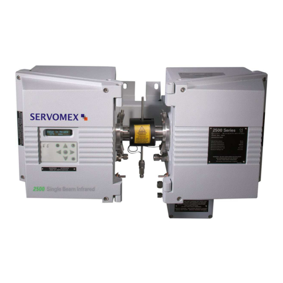
- Page 1 SERVOTOUGH SpectraExact 2500 QUICK START MANUAL Part Number: 02500003E Revision: Language: UK English...
- Page 2 Servomex 2500 Quick Start Manual 2500 Series - Configuration and Operation 02500/003E/0...
- Page 3 Servomex 2500 Quick Start Manual 2500 Series - Configuration and Operation 02500/003E/0...
- Page 4 Servomex 2500 Quick Start Manual 2500 Series - Configuration and Operation 02500/003E/0...
-
Page 5: Table Of Contents
Servomex 2500 Quick Start Manual INTRODUCTION ......................6 Warnings, Cautions and Notes ................6 About this manual ....................6 Introduction to the user interface ................8 INITIAL CONFIGURATION ..................9 Power up procedure ....................9 General access to analyser functions ..............9 Setting passwords .................... -
Page 6: Introduction
Servomex 2500 Quick Start Manual INTRODUCTION 1.1 Warnings, Cautions and Notes This publication includes WARNINGS, CAUTIONS and NOTE which provide information relating to the following: WARNINGS Hazards which could result in personal injury or death. CAUTIONS Hazards which could result in equipment or property damage. - Page 7 Servomex 2500 Quick Start Manual KEY TO FIGURES Figure A Analyser Front View 1. 16 Character 2 line VF Display 2. Hard key to select Measurement Display 3. Hard key to select Menu Display 4. Hard key to exit to the previous menu level 5.
-
Page 8: Introduction To The User Interface
Servomex 2500 Quick Start Manual 1.3 Introduction to the user interface See Figure A. The keypad and display used on the 2500 series analysers have been designed to be easy to operate and have a minimum number of keys. There are only 4 single-function (‘hard’) keys: MEASURE;... -
Page 9: Initial Configuration
Servomex 2500 Quick Start Manual INITIAL CONFIGURATION 2.1 Power up procedure WARNING Ensure that the instrument variant is properly installed before proceeding. Confirm that all electrical and plumbing connections have been correctly made as described in the installation manual. Follow the Power up procedure as detailed in the installation manual. -
Page 10: Setting Passwords
Servomex 2500 Quick Start Manual will often be necessary to enter the password. NOTE The factory-default password for the 2500 series is ‘2000’ - this must be entered. Alternatively, if a keyswitch has been fitted this should now be closed. Failure to close the keyswitch is interpreted as an invalid password, and this should prompt the user to operate the keyswitch at this point. -
Page 11: Setting Time And Date
Servomex 2500 Quick Start Manual Go via MENU/SET UP/UTILITY/UTILITY 1 to NEW PASS - Press ENTER At display screen Operation SUPERVISOR Select required password and press ‘ENTER’ OPERATOR NEW SUPERVISOR Use the cursor keys to set the new password, PASS 00 0 0 then press ‘ENTER’... -
Page 12: Main Configuration
Servomex 2500 Quick Start Manual MAIN CONFIGURATION 3.1 Alarms There are 4 concentration alarms for each measured component on the 2500 series, and these are called ‘AL1’, ‘AL2’, ‘AL3’ and ‘AL4’. These must now be set up to suit the measurement and control needs of the particular installation. -
Page 13: Allocation Of Relays
Servomex 2500 Quick Start Manual 3.2 Allocation of relays Each standard 2500 series analyser has 3 relay outputs, which can now be assigned to various functions. These relay outputs are given software identity numbers which relate physically to the particular PCB from which they are provided. The hardware locations and terminal strip identifiers are given in the installation manual. - Page 14 Servomex 2500 Quick Start Manual Go via MENU/SET UP/ASSIGN to RELAYS - Press ENTER At display screen Operation SELECT RELAY Select required relay using cursor keys, then press 'ENTER' 1.3 ASSIGNED ↑ or 1.3 UNASSIGNED ↑ RELAY ASSIGNMENT Select 'EDIT' to edit allocation, or re-assign a cleared relay or 1.3 EDIT / CLEAR...
-
Page 15: Analogue Outputs
Servomex 2500 Quick Start Manual 3.3 Analogue outputs Each standard 2500 series analyser has 2 analogue outputs, which can now be assigned to the measurement being made. These analogue outputs are given software identity numbers which relate physically to the particular PCB from which they are provided. -
Page 16: Defining And Selecting Measurement Display Screen
Servomex 2500 Quick Start Manual The analogue identity (in this case ‘1.1’) appears lower left, and the current status (ASSIGNED OR UNASSIGNED) next to it. All are initially ASSIGNED in the factory to the measurements in logical order, one analogue per measurement. -
Page 17: Communication Options
Servomex 2500 Quick Start Manual If SINGLE display is selected, the name of a chosen measured component appears on the top line and the measurement value on the bottom line. The SPLIT display is used on multi component analysers only, and is used to show two measured components at a time. -
Page 18: Communication Setup
Servomex 2500 Quick Start Manual Ethernet enables Modbus TCP communication using Ethernet interface on the 02500913 Communication Board (if fitted) WARNING Do not use an uncertified DCS, dilatator, printer or other external equipment in a Hazardous Area. 3.6 Communication Setup When the communication mode has been selected as described in section 3.5, it may... - Page 19 Servomex 2500 Quick Start Manual At display screen Operation Select required value then press ‘ENTER’ SYSTEM SET-UP OR IDENTITY HISTORY 2500 Series - Configuration and Operation 02500/003E/0...
-
Page 20: Modbus Ascii
Servomex 2500 Quick Start Manual 3.8 MODBUS ASCII This section details the analyser configuration that is displayed when the communications mode is set to MODBUS ASCII. This should be adjusted as necessary to match the requirements of the Modbus network to which the analyser is connected. -
Page 21: Functions
Servomex 2500 Quick Start Manual 3.11 Functions The FUNCTIONS menu items are displayed in turn for the selected component, so that they can be locked ON/OFF, or DEFAULT/USER, as required. Pressure Compensation - If the 2500 is fitted with optional Sample Pressure Compensation, this may be turned ON or OFF using this function. - Page 22 Servomex 2500 Quick Start Manual Go via MENU/SETUP/UTILITY/UTILITY 2 - Press ENTER At display screen Operation SELECT COMPONENT Select required component, then press ‘ENTER’ vpm ↑ (if more than 1 component) ZERO & SPAN TOL Select ‘FUNCTIONS’, then press ‘ENTER’...
-
Page 23: Associate
Servomex 2500 Quick Start Manual 3.12 Associate The ASSOCIATE function is the procedure by which the factory calibration and system information in a 2500 is uploaded from the backup EEPROM on the Transmitter PCB into the 2500's Microprocessor PCB. This routine is normally used if a replacement Microprocessor PCB is being fitted. -
Page 24: Calibration
CALIBRATION 4.1 Introduction to calibration The 2500 series is supplied by Servomex with an accurate factory calibration for the measurement required as specified on the customer's order. This calibration contains a zero constant, a span constant and a linearising function, which are stored in the 2500 and cannot be erased or overwritten by the user. -
Page 25: Manual Calibration And Checking
Servomex 2500 Quick Start Manual Go via MENU/SETUP/UTILITY/UTILITY 2 to Z&S TOL - Press ENTER At display screen Operation ZERO TOLERANCE Select required value using cursor keys, then press ‘ENTER’ 10.0 % FSD SPAN TOLERANCE Select required value using cursor keys, then press ‘ENTER’... -
Page 26: Auto Calibration And Autocheck Setup
Servomex 2500 Quick Start Manual • Checking Manual Checking of Zero and Span is conducted by entering CHK Z & S routine. This routine operates the Solenoid Valve Drives 1 and 2. Therefore, if the 2500 is configured and plumbed for AUTOCALIBRATION or AUTOCHECKING, the Zero Calibration Sample and Span Calibration Sample connected for automatic routines will also be used in the Manual Check Zero and Span routine. - Page 27 Servomex 2500 Quick Start Manual iii) Remotely, on demand. Remote contact closure by host device or remote user switch will initiate one complete Auto calibration operation (a ‘ONE CYCLE’) only; see installation manual for wiring. Contacts must be closed for at least 2 seconds but no more than 59 seconds.
- Page 28 Servomex 2500 Quick Start Manual Go via MENU/CALIBRATE to AUTO - Press ENTER At display screen Operation SET UP CAL PARM Select required function, then press ‘ENTER’ ONE CYCLE SELECT AUTO CAL Select required state, then press ‘ENTER’ LOW / LOW & HIGH [Measurement] Set to the required zero gas concentration, then press ‘ENTER’...
-
Page 29: Calibration When Learnt Cross Interference Is Enabled
Servomex 2500 Quick Start Manual NOTE • If Auto calibrations are to be remotely initiated, it is advisable to prevent internal initiation by setting the auto calibration PERIOD to 00 days, 00 hrs. • Timed or remotely-initiated Auto calibrations will NOT operate when there is any Fault condition or during the warming-up period, or 15 minutes after the clearance of the last Fault or warm-up. -
Page 30: Viewing Configuration And History Files
Servomex 2500 Quick Start Manual VIEWING CONFIGURATION AND HISTORY FILES 5.1 Displaying ‘current’ alarms and faults • Alarms Go via MENU/ALARMS to DISPLAY ALARMS - Press ENTER At display screen Operation Either ‘NO ALARMS DETECTED’ OR the first alarm is NO ALARMS DETECTED displayed;... -
Page 31: Displaying Alarm Settings
Servomex 2500 Quick Start Manual 5.2 Displaying alarm settings Go via MENU/SET UP/DISPLAY to ALARMS - Press ENTER At display screen Operation SELECT COMPONENT select the desired component for alarm display, then press vpm ↑ ‘ENTER' (if more than 1 component) -
Page 32: Displaying Analyser Histories
Servomex 2500 Quick Start Manual 5.4 Displaying analyser histories The 2500 series retains history entries (up to 20 per category) for the following events. The most recent event is shown first. Alarms: An entry is made each time an alarm appears (‘ON’) or is cleared (‘OFF’), in the following format: [Measurement] [Alarm No.] [Event] [Time] [Date]... -
Page 33: Displaying Analyser Identity And Diagnostics
Servomex 2500 Quick Start Manual Go via MENU/CALIBRATE to MANUAL CAL - Press ENTER At display screen Operation Select the desired measurement history to display, then press SELECT COMPONENT vpm ↑ ‘ENTER' (if more than 1 component) Z CAL/S CAL Select ‘HISTORY', then press ‘ENTER'...
Need help?
Do you have a question about the SERVOTOUGH SpectraExact 2500 and is the answer not in the manual?
Questions and answers