Table of Contents
Advertisement
Quick Links
User Manual
Thank you for purchasing our product. If there are any
questions, or requests, do not hesitate to contact the
dealer.
This manual may contain several technical incorrect
places or printing errors, and the content is subject to
change without notice. The updates will be added to
the new version of this manual. We will readily improve
or update the products or procedures described in the
manual.
TVIVD-PR5EXIR28
Advertisement
Table of Contents

Subscribe to Our Youtube Channel
Related Manuals for Security Camera King TVIVD-PR5EXIR28


Summary of Contents for Security Camera King TVIVD-PR5EXIR28
- Page 1 TVIVD-PR5EXIR28 User Manual Thank you for purchasing our product. If there are any questions, or requests, do not hesitate to contact the dealer. This manual may contain several technical incorrect places or printing errors, and the content is subject to change without notice.
- Page 2 Regulatory Information FCC Information Please take attention that changes or modification not expressly approved by the party responsible for compliance could void the user’s authority to operate the equipment. FCC compliance: This equipment has been tested and found to comply with the limits for a Class A digital device, pursuant to part 15 of the FCC Rules.
- Page 3 Safety Instruction These instructions are intended to ensure that user can use the product correctly to avoid danger or property loss. The precaution measure is divided into “Warnings” and “Cautions”. Warnings: Serious injury or death may occur if any of the warnings are neglected.
- Page 4 1 Introduction 1.1 Product Features The camera is applicable for both indoor and outdoor conditions, and the application scenarios include road, warehouse, underground parking lot, bar, etc.. The main features are as follows: High performance CMOS sensor Low illumination, 0.01 Lux @ (F1.2, AGC ON), 0 Lux ...
-
Page 5: Installation
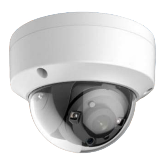
1.2.3 Overview of Type III Camera Power Cord 12 VDC Mounting Video Cable TVI Base Tilt Adjusting IR LED Photoresistor Screw Black Liner Bubble Safty Rope Figure 1-3 Overview of Type III Camera 2 Installation Before you start: Make sure that the device in the package is in good ... - Page 6 Figure 2-2 Drill Template Note: Drill the cable hole, when adopting the ceiling outlet to route the cable 5. Attach the mounting base to the ceiling/wall, and secure them with supplied screws. Figure 2-3 Attach the Mounting Base to the Ceiling Note: The supplied screw package contains self-tapping ...
- Page 7 2.1.2 Mounting with Inclined Base Steps: 1. Paste the drill template (supplied) to the place where you want to install the camera. 2. Drill screw holes, and the cable hole on the ceiling/wall according to the supplied drill template. Figure 2-6 The Drill Template 3.
- Page 8 Steps: 1. Disassemble the turret camera by rotating the camera to align the notch to the clip plate, as shown in the Figure 2-10. Clip Plate Notch Figure 2-10 Disassemble the Camera 2. Pry the mounting base to remove the mounting base from the camera body.
- Page 9 Pan Position [0° to 360°] Tilt Position Rotation Position [0°to75°] [0° to 360°] Figure 2-14 3-axis Adjustment 1). Hold the camera body and rotate the enclosure to adjust the pan position [0° to 360°]. 2). Move the camera body up and down to adjust the tilt position [0°...
- Page 10 Junction Box Body Junction Box Body Junction Box Cover Figure 2-16 Fix the Gang Box 7. Repeat steps 6 to 9 of 2.1.1 Ceiling/Wall Mounting without Junction Box to install the camera to the junction box. 2.3.2 Wall Mounting Before you start: You need to purchase a wall mounting bracket separately.
-
Page 11: Adjusting Screw
Hole A: for cables routed through the ceiling screw hole 1: for Mounting Base Figure 2-19 Drill Template Note: Cable hole is required, when adopting the ceiling outlet to route cables. 3. Loosen the set screws with a hex wrench (supplied) to remove the bubble. -
Page 12: Menu Description
2). Hold the black liner to adjust the pan position [0° to 355°]. 3). Hold the camera body to adjust the rotation position [0° to 355°]. 8. Reinstall the bubble, and tighten the screws. Figure 2-23 Bubble Reinstallation 3 Menu Description Purpose: Call the menu by clicking the button on the PTZ... - Page 13 5. Click the direction arrow to control the camera. 1). Click up/down direction button to select the item. 2). Click Iris + to confirm the selection. 3). Click left/right direction button to adjust the value of the selected item. 3.1 OUTPUT MODE In the OUTPUT MODE submenu, you can set RESOLUTION, FRAME RATE, and NTSC/PAL.
-
Page 14: Anti-Flicker
You can set the brightness value from 1 to 10 to darken or brighten the image. The higher the value, the brighter the image is. EXPOSURE MODE You can set the EXPOSURE MODE as GLOBAL, or BLC. GLOBAL GLOBAL refers to the normal exposure mode which performs exposure according to the whole image brightness. -
Page 15: Video Settings
COLOR The image is colored in day mode all the time. The image is black and white all the time, and the IR LED turns on in the poor light conditions. AUTO Automatically switch Color or BW (Black and White) according to actual scene brightness You can turn on/off the INFRARED and set the value of SMART IR in this menu. -
Page 16: Save And Exit
conditions and delivering more accurate and sharp image quality. You can set the DNR value from 1 to 10. MIRROR DEFAULT, H, V, and HV are selectable for mirror. DEFAULT: The mirror function is disabled. H: The image flips 180° horizontally. V: The image flips 180°...
Need help?
Do you have a question about the TVIVD-PR5EXIR28 and is the answer not in the manual?
Questions and answers