
Subscribe to Our Youtube Channel
Related Manuals for Omega HHF141 Series


Summary of Contents for Omega HHF141 Series
- Page 1 User’ s Gui d e Shop online at omega.com e-mail: info@omega.com For latest product manuals: omega.com/en-us/pdf-manuals HHF141 Series Handheld Rotating High-Accuracy Metal-Vaned Digital Anemometers M4745/1222 Page 1 of 24...
- Page 2 For Other Locations Visit omega.com/worldwide The information contained in this document is believed to be correct, but OMEGA accepts no liability for any errors it contains and reserves the right to alter specifications without notice. M4745/1222 Page 2 of 24...
-
Page 3: Important Safety Information
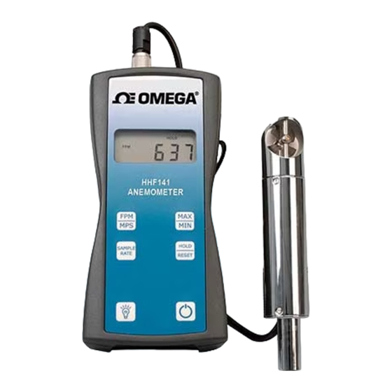
INTRODUCTION Omega’s Model HHF141 digital anemometer is a versatile instrument for measuring air velocity in various applications such as HVAC, aerospace development, industrial process airflow, and fluids research. The rugged yet precise probes can be used for airstreams that have a wide range of humidity, temperature, and contaminants without compromising accuracy. -
Page 4: Compliance Information
COMPLIANCE INFORMATION FCC Compliance Statement This equipment has been tested and found to comply with the limits for a Class B digital device, pursuant to part 15 of the FCC rules. These limits are designed to provide reasonable protection against harmful interference. This equipment generates, uses, and can radiate radio frequency energy and, if not installed and used in accordance with the instructions, may cause harmful interference to radio communications. - Page 5 DANGER Never touch the vane assembly blades and/or thermal sensors. The vane assembly blades may contain sharp edges which may cause minor cuts. The assembly contains precision bearings which are sensitive, and the blades are finely adjusted to specific pitches. Touching this assembly or its parts may cause damage which can affect its operation and the calibration.
- Page 6 CAUTION (continued) Never disassemble, modify, or repair the product. Failure to observe the above may cause damage to the instrument or the probe. It may also void the manufacturer’s warranty and calibration certificate. Do not pick up or carry the instrument by the cable. It may cause a malfunction or damage to the wiring of the cable.
-
Page 7: Section 1 - Specifications
SECTION 1 - SPECIFICATIONS Ranges: Probe AP275: 50 to 7800 ft/min (feet per minute) 0.25 to 39.60 m/sec (meters per second) Air Probe AP100: 300 to 6890 ft/min (1.50 to 35.00 m/sec) Accuracy: AP275: ±1.0% of reading ±1 digit in FPM AP100: ±0.5% full scale ±0.75% of reading ±1 digit in FPM Resolution: 1 ft/min or 0.01 m/sec... -
Page 8: Options Available
OPTIONS AND COMPONENTS Options Available: Protective Boot and Splash-Proof Seal for the Instrument • USB Communications • RS232 Communications • Analog 0-5 Volt Output • Wall Transformer Power for the Instrument (US only) • Additional Probes, 2.75-inch diameter or 1 inch diameter •... - Page 9 DIMENSIONS INSTRUMENT 2.75 INCH PROBE 1 INCH PROBE M4745/1222 Page 9 of 24...
-
Page 10: Section 2 - Switch Functions
SECTION 2 – SWITCH FUNCTIONS Pressing the ON/OFF key switches the instrument ON. Hold down the key for 2 seconds to switch the unit OFF. The unit will automatically power off after 30 minutes without any key presses. To disable auto power-off, hold down the power button during turn-on. The unit will flash AOFF, which means that the auto power-off has been disabled. - Page 11 SECTION 2 – SWITCH FUNCTIONS (continued) Press the SAMPLE RATE key to change the measurement averaging rate (“sample rate”) of the unit: 2 sec An average value of airspeed measurements during the preceding 2 seconds is displayed. 4 sec An average value of airspeed measurements during the preceding 4 seconds is displayed.
-
Page 12: Appendix A - Lcd Display Symbols
APPENDIX A – LCD DISPLAY SYMBOLS APPENDIX B – BATTERY REPLACEMENT M4745/1222 Page 12 of 24... -
Page 13: Appendix C - Airflow Volume Calculations
APPENDIX C – AIRFLOW VOLUME CALCULATIONS To calculate cubic feet per minute (CFM) from a measured air velocity (FPM), you need the calculated cross-sectional area of the air flow stream: Volume Flow (CFM) = Velocity (FPM) X Area (sq ft). In a rectangular duct this cross-sectional area equals the Width times the Height. -
Page 14: Appendix D - Analog Outputs (If Equipped)
► With the additional error associated with the analog output voltage, the effective accuracy of the analog output for this air velocity measurement will be ±2% of reading ±1 digit (±11 FPM). Custom Analog Voltage Outputs are also available – contact Omega for details. M4745/1222 Page 14 of 24... - Page 15 APPENDIX D – continued Analog Output circuit block diagram and connector pin assignment Mating Cable Connector: Binder Part No. 99-0413-00-05 M4745/1222 Page 15 of 24...
-
Page 16: Appendix E - Usb Data Output (If Equipped)
APPENDIX E - USB DATA OUTPUT (IF EQUIPPED) If the instrument is equipped with the USB Communications option, there will be a four-pin male connector on the bottom of the instrument. Also, a USB cable will be included with the instrument. This cable will have a four-pin female connector on one end and a USB Type-A connector on the other end. - Page 17 APPENDIX E – continued You are now ready to capture the data being measured by your instrument. Please refer to Appendix G – Viewing and Capturing Data for further instructions. NOTE: Units with USB or RS232 communications, output only Air data at this time.
-
Page 18: Appendix F - Rs232 Communications (If Equipped)
APPENDIX F – RS232 COMMUNICATIONS (IF EQUIPPED) If the instrument is equipped with the RS232 Communications option, there will be a three-pin male connector on the bottom of the instrument. Also, an RS232 cable will be included with the instrument. This cable will have a three-pin female connector on one end and a DB9 Female connector on the other end. -
Page 19: Appendix G - Viewing And Capturing Data
There are many terminal emulator programs available on the market. It is up to the end-user to determine which program is compatible with his/her system, what settings it may require, and the Omega Engineering product being used. Omega Engineering does not endorse or recommend any of these programs and assumes no liability for their use. - Page 20 APPENDIX G – continued You will now receive data from your instrument. The graphic below shows the serial port output data from Parallax Serial Terminal when connected to an Omega HHF141 Instrument. Graphics may vary. M4745/1222 Page 20 of 24...
- Page 21 Comma-Separated Values (CSV) Measurement Units Same as Units shown on LCD Display Below are examples of the formatted output data for Omega Engineering HHF141-HHF144 Series Instruments (units may be different depending on the units selected on the LCD display): Model HHF141:...
- Page 22 APPENDIX G – continued Exporting and Graphing Data Exporting serial port instrument data from the Pacer Instrument to a spreadsheet application such as Microsoft Excel or OpenOffice Calc allows the data to graphed or recorded. The simplest way to export the instrument data is to use a terminal emulator program, like Parallax Serial Terminal, and either capture the serial data/text to a file (menu selection) or to manually highlight, copy, and then paste the instrument data into an editor such as Windows Notepad.
- Page 23 Department will issue an Authorized Return (AR) number immediately upon phone or written request. Upon examination by OMEGA, if the unit is found to be defective, it will be repaired or replaced at no charge. OMEGA’s WARRANTY does not apply to defects resulting from any action of the purchaser, including but not limited to mishandling, improper interfacing, operation outside of design limits, improper repair, or unauthorized modification.
- Page 24 Where Do I Find Everything I Need for Process Measurement and Control? OMEGA…Of Course! Shop online at omega.com TEMPERATURE M U Thermocouple, RTD & Thermistor Probes, Connectors, Panels & Assemblies M U Wire: Thermocouple, RTD & Thermistor M U Calibrators & Ice Point References M U Recorders, Controllers &...
Need help?
Do you have a question about the HHF141 Series and is the answer not in the manual?
Questions and answers