
Related Manuals for SeeEyes SC-IPC07PU


Summary of Contents for SeeEyes SC-IPC07PU
- Page 1 Release Version 1.2 1Channel IP Over UTP Transmission Solution SC-IPC07PU User’s Manual TRANSMITTER RECEIVER...
- Page 2 Release Version 1.2 Precaution and Safety Guidelines The content of this guideline is to protect the safety of users and prevent property damage. Be sure to read this user’s manual thoroughly and use the device correctly. Warning (If you do not keep any of the below guidelines, you may get seriously injured or cause somebody’s death.) Be sure to install the product after unplugging power cord.
-
Page 3: Network Cable Diagram
Release Version 1.2 Caution (If you do not keep any of the below guidelines, you may get injured or suffer property loss.) ■ Proper ambient temperature and humidity are recommended. - Avoid extremely high temperatures(over 50°C) or low(below -10°C), and humid conditions. ■... - Page 4 1. Introduction 1-1. Overview SC-IPC07PU, which consists of 1CH Transmitter and 1CH Receiver, transmits Ethernet data and power over one UTP cable. Its built-in power supply function (IEEE802.3at) operates a transmitter and a PoE camera from the receiver side without separate power lines and it resolves short-distance typical network system by transmitting Ethernet data in a long distance.
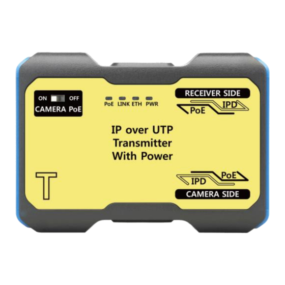
- Page 5 Release Version 1.2 3. Product Parts and Functions 3-1. Transmitter ② ① ③ ④ ① CAMERA PoE: Switch to set power supply to PoE IP camera. ※ In case of connecting PoE IP camera, set CAMERA PoE switch as ON. ※...
- Page 6 Release Version 1.2 3-2. Receiver ③ ① ② ④ ⑤ ① NVR SIDE: Port to connect NVR or PoE Hub. ② TRANSMITTER SIDE: Port to connect Transmitter and input video. ③ DC 48~56V IN: Port to input DC adapter (48V or 56V) power. ※...
-
Page 7: Connection Diagram
Release Version 1.2 4. Connection Diagram 4-1. In case of connecting PoE IP Camera (TX’s PoE Switch ON) <Installation Guide> ① Set Transmitter’s CAMERA PoE switch to ON. (PoE LED On) ※ In case of connecting non PoE camera, set transmitter’s CAMERA PoE switch to OFF. CAMERA PoE switch OFF ②... -
Page 8: Specifications
Release Version 1.2 5. Specifications MODEL Transmitter Power Input PoE (PoE input from Receiver) Power Output Midspan PoE (Type B Only, PoE SW On/Off available) Transmission Bandwidth 100Mbps RECEIVER SIDE RJ-45 (TIA/EIA568B Type) Connection Port CAMERA SIDE RJ-45 (TIA/EIA568B Type) RED LED GREEN LED LED Indicator... -
Page 9: Power Output
Release Version 1.2 6. Power Output (Calculated Value) Cable Transmission Transmission With With Cable Loop Distance (CAT.5e) Bandwidth DC48V 1A Adapter DC56V 1.16A Adapter Resistance 100m 100Mbps 18.2Ω 200m 100Mbps 17.2W 36.2Ω 300m 100Mbps 11.4W 54.7Ω 400m 100Mbps 8.6W 16.6W 72.9Ω... -
Page 10: Troubleshooting
Release Version 1.2 8. Trouble Shooting Symptom Checking Method <Transmitter> • Check if PoE LED on Receiver and PWR LED on Transmitter is ON. • Check the connection status of UTP cable. No Power <Receiver> • Check if the PWR LED is working properly. •... -
Page 11: Warranty Certificate
Release Version 1.2 9. Warranty Certificate Product No. Model No. Date of Purchase Place of Purchase Name Purchaser Address & Contact No. Name Distributor Address & Contact No. Warranty Period Two(2) years from the date of purchase Any failure that occurs in the normal use for only two years after purchase will be repaired free of charge. - Page 12 Release Version 1.2 SeeEyes Co., Ltd #5F, Sunil Technopia, 555 Dunchon-daero, Jungwon-gu, Seongnam City, Gyeonggi Province, Korea (Zip Code: 13215) TEL: +82-(0)31-730-5833 FAX: +82-(0)31-777-3512 EMAIL: global@sscctv.com http://www.sscctv.com/eng...
Need help?
Do you have a question about the SC-IPC07PU and is the answer not in the manual?
Questions and answers