Table of Contents
Advertisement
Quick Links
Declaration of Conformity
According to 47 CFR, Parts 2 and 15 of the FCC Rules
is a Class B digital device that complies with 47 CFR Parts 2 and 15 of the FCC
Rules. Operation is subject to the following two conditions:
1. This device may not cause harmful interference.
2. This device must accept any interference received, including interference
that may cause undesired operation.
This declaration is given to the manufacturer:
CHAINTECH-EXCEL COMPUTER INC.
4427 Enterprise St. Fremont, CA 94538, U.S.A.
The following designated product:
EQUIPMENT : MAINBOARD
MODEL NO. : 6AIV2
http://www.chaintech-excel.com
Chaintech President: Simon Ho
Signature:
Advertisement
Table of Contents

Related Manuals for CHAINTECH 6AIV2


Summary of Contents for CHAINTECH 6AIV2
- Page 1 According to 47 CFR, Parts 2 and 15 of the FCC Rules The following designated product: EQUIPMENT : MAINBOARD MODEL NO. : 6AIV2 is a Class B digital device that complies with 47 CFR Parts 2 and 15 of the FCC Rules. Operation is subject to the following two conditions: 1.
- Page 2 Federal Communications Commission Statement This device complies with FCC Rules Part 15. Operation is subject to the following two conditions: This device may not cause harmful interference This device must accept any interference received, including interference that may cause undesired operation. This equipment has been tested and found to comply with the limits for a Class B digital device, pursuant to Part 15 of the FCC Rules.
-
Page 3: Table Of Contents
Table of Contents Chapter 1 Introduction ................ 1 Product Specifications ............1 Package Contents ..............3 Mainboard Layout ..............4 Connector and Jumper Reference Chart ......5 Chapter 2 Hardware Setup ..............6 Installing a CPU in a Socket 370 .......... 6 Setting Your CPU's Parameter........ -
Page 4: Chapter 1 Introduction
Introduction Chapter 1 Introduction 1-1 Product Specifications... - Page 5 Chapter 1...
-
Page 6: Package Contents
Introduction 1-2 Package Contents See the Readme.txt file in the CD-ROM's root directory for installation instructions of all driver and software utilities. Figure 1-1 IDE UDMA-66/100 cable Figure 1-2 Standard Floppy cable... -
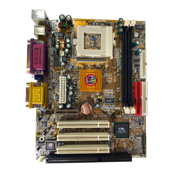
Page 7: Mainboard Layout
Chapter 1 1-3 Mainboard Layout... -
Page 8: Connector And Jumper Reference Chart
Introduction 1-4 Connector and Jumper Reference Chart Jumper & Function Page Connector No. Clear CMOS Data JP2A/JP2B External Clock Frequency Frequency Ratio Setting (Optional) Power On By Keyboard Power On By USB JP11 Onboard LAN Over Ride Power Button connector Power Indicator LED connector System Reset Switch connector Speaker connector... -
Page 9: Chapter 2 Hardware Setup
Chapter 2 Chapter 2 Hardware Setup Be sure to disconnect the power cable from the power source before performing any work on your mainboard, i. e. installing a CPU, memory module, changing a jumper setting, etc. Not doing so may result in electrical shock! 2-1 Installing a CPU in a Socket 370 Installing a heat sink with cooling fan is necessary for proper heat dissipation from your CPU. -
Page 10: Connector And Jumper Settings
Hardware Setup 2-3 Connector and Jumper Settings The power supply connector is the last connection to be made while installing a mainboard. Before connecting the power supply, please make sure it is not connected to the power source. ATX Power Supply Connector (PW1) Software Power-Off Control Power-On By Modem Blinking LED in Suspend Mode... -
Page 11: Over-Ride Power Button
Chapter 2 Front Panel Connector Set (CN1) A through F A. Over-ride Power Button Connector Over-ride Power Button B. Power Indicator LED Connector C. Green Switch Connector D. System Reset Switch Connector E. Speaker Connector F. IDE Activity LED Connector... - Page 12 Hardware Setup Clear CMOS Data (JP1) Definition Normal (default) Clear CMOS Data External Clock Frequency (JP2A/JP2B) JP2A JP2B Auto 100MHz Open 133MHz Open Open Optional Frequency Ratio Setting (JP4) RATIO SHORT OPEN SHORT OPEN SHORT OPEN SHORT OPEN SHORT OPEN SHORT OPEN OPEN...
-
Page 13: Wake Up On Lan
Chapter 2 Onboard LAN (JP11) This function allows you to enable and disable the on board LAN. You must set the jumper's cap to pins 1-2 to enable or ISOLATEB set pins 2-3 to disable this function. CD-ROM Audio-in (CN2) Auxiliary Audio-in (CN3) Audio Mono-in/out (CN4) This connector is used for Add on Card e.g. -
Page 14: Main Memory Configuration
Hardware Setup Optional TV-Out/DFP Connectors (CN18) VC C T VD 0 T VD 1 VC C 3 T VD 2 T VD 3 G N D T VD 4 T VD 5 VC C 3 T VD 6 -PC IR S T T VD 7 T VVS T VHS... -
Page 15: Chapter 3 Award Bios Setup Program
User's Manual Chapter 3 3 3 3 3 3 Award BIOS Setup Program Award's BIOS ROM has a built-in setup program that allows users to modify the basic system configuration. This information is stored in CMOS RAM so that it can retain the setup information, even when the power is turned off. -
Page 16: Standard Cmos Setup
Award BIOS Setup Program 3-1 Standard CMOS Features The Standard CMOS Features allows users to configure system components such as hard disk drive, floppy disk drive and video display as well as date, time and boot up error signaling. This configuration menu should be changed when installing a mainboard for the first time, changing hardware in your system such as the HDD, FDD, video display, or when the CMOS data has been lost or contaminated. - Page 17 User's Manual Floppy Disk Drives Choose the memory capacity and disk size that corresponds with that of your floppy disk drive(s). Video Select the type of video adapter present in your system. You can ignore this setting if you are using a VGA monitor since VGA BIOS automatically configures this setting. Halt When the system is powered on, BIOS performs a series of diagnosis tests called POST (Power On Self Test).
-
Page 18: Advanced Bios Features Setup
Award BIOS Setup Program 3-2 Advanced BIOS Features By choosing the Advanced BIOS Features option from the CMOS Setup Utility menu (Figure 3-1), the screen below is displayed. This sample screen contains the manufacturer's default values for the mainboard. CMOS Setup Utility- Copyright (C) 1984-2001 Award Software Advanced BIOS Features Item Help Anti-Virus Protection... - Page 19 User's Manual B. Cache Control CPU Internal Cache/External Cache Cache memory is much faster than conventional DRAM system memory. These fields allow you to enable or disable the CPUs Level 1 built-in cache and Level 2 external cache. Both settings are left enabled to significantly increase the performance of your computer.
- Page 20 Award BIOS Setup Program Typematic Delay (Msec) The typematic delay sets how long after you press a key that a character begins repeating. E. Security Option The Supervisor and/or User Password functions shown in Figure 3-1 must be set to take advantage of this function. See Section 3-11 for password setting information.
-
Page 21: Advanced Chipset Setup
User's Manual 3-3 Advanced Chipset Features By choosing the Advanced Chipset Features option from the CMOS Setup Utility menu (Figure 3-1), the screen below is displayed. This sample screen contains the manufacturer's default values for the mainboard. CMOS Setup Utility- Copyright (C) 1984-2001 Award Software Advanced Chipset Features Item Help DRAM Clock... - Page 22 Award BIOS Setup Program C. SDRAM Cycle Length When synchronous DRAM is installed, the number of the clock cycles of CAS latency depends on the DRAM timing. Do not reset this setting from the default value specified by the system designer. D.
- Page 23 User's Manual I. OnChip Sound This function must be enabled in order to use the onboard audio function. To terminate this function set it to disabled. J. OnChip Modem This function must be enabled in order to use the soft modem riser card on AMR slot(optional).
-
Page 24: Integrated Peripherals
Award BIOS Setup Program 3-4 Integrated Peripherals This section provides information on setting peripheral devices. By choosing the Integrated Peripherals option from the CMOS Setup Utility menu (Figure 3-1), the screen below is displayed. This sample screen contains the manufacturer's default values for the mainboard. - Page 25 User's Manual C. OnChip USB Enable the on-board Universal Serial Bus (USB) controller if you want to connect a USB keyboard to your system. Note that if this setting is disabled, you can still temporarily use a USB keyboard during bootup so that you can enter BIOS and enable this setting.
-
Page 26: Power Management Setup
Award BIOS Setup Program 3-5 Power Management Setup This section provides information on the Green PC power management functions. By choosing the Power Management Setup option from the CMOS Setup Utility menu (Figure 3-1), the screen below is displayed. This sample screen contains the manufacturer's default values for the mainboard CMOS Setup Utility- Copyright (C) 1984-2001 Award Software Power Management Setup... -
Page 27: Power On By Alarm
User's Manual D. Video Off Method This function serves as both a screen saver and power saver for monitors. See the next function, Video Off After, for setting the video timer. Blank - BIOS will only blank the monitor's screen. The electricity saved in this mode is negligible and this function is only used as a screen saver to prevent screen damage while the screen is on but not in use. -
Page 28: Pnp/Pci Configuration
Award BIOS Setup Program 3-6 PNP/PCI Configuration This section provides IRQ and DMA setting information. By choosing the PNP/ PCI Configuration option from the CMOS Setup Utility menu (Figure 3-1), the screen below is displayed. This sample screen contains the manufacturer's default values for the mainboard. -
Page 29: Pc Health Status
User's Manual 3-7 PC Health Status By choosing the PC Health Status option from the CMOS Setup Utility menu (Figure 3-1), the screen below is displayed. This field shows you the current system temperature/external voltages input and the current CPU FAN and System FAN operating speed. -
Page 30: Load Fail-Safe Defaults
Award BIOS Setup Program 3-9 Load Fail-Safe Defaults Load Fail-Safe Defaults loads the default BIOS values directly from the CMOS Setup Utility menu (Figure3-1). If the stored record created by the setup program becomes corrupted and therefore unusable, these defaults will be loaded automatically when you turn on the computer. -
Page 31: Supervisor Password & User Password Setting
User's Manual 3-11 Supervisor Password & User Password Setting There are four different variables that control password settings. The first two are located under the Security Option function in BIOS Features Setup Menu (Figure 3-1). When the Security Option function is set to Setup, a password is required to enter BIOS and change BIOS settings. -
Page 32: Appendix Embedded Flash Utility
Appendix Embedded Flash Utility This mainboard is equipped with an Erasable Flash ROM and an Embedded Flash Utility which allows the user to update the BIOS to a newer version. Embedded Flash Utility eases BIOS upgrade and eliminate the compatibility issue between different Flash ROM type and version of Flash utility.
Need help?
Do you have a question about the 6AIV2 and is the answer not in the manual?
Questions and answers