Table of Contents
Advertisement
Quick Links
P/N 9850-000183-02
General Information
• Read all instructions on both sides of this
• Install in accordance with ALL local codes
sheet first
• For indoor use only
Specifications
Power Requirements:
277 VAC:
120 to 347 VAC, 50/60 Hz - Neutral Required
• Fluorescent/Ballast - 0 to 2700W, 50/60 Hz
120 VAC:
347 VAC:
• Incandescent/Tungsten - 0 to 800W, 50/60 Hz
• Fluorescent/Ballast - 0 to 1500W, 50/60 Hz
• Fluorescent/Ballast - 0 to 1200W, 50/60 Hz
Operating Environment:
Motor Load: ¼ HP @ 125 VAC
• Temperature: 32° F – 104° F (0° C – 40° C)
230 VAC:
• Relative Humidity: up to 90% non-condensing
• Fluorescent/Ballast - 0 to 1200W, 50/60 Hz
Description
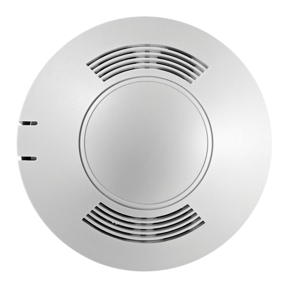
The OAC-U Ceiling Mount Line Voltage Occupancy Sensor is an Ultrasonic (US) motion sensing lighting control,
used for energy savings and convenience. The sensor produces a low intensity, inaudible sound to detect occupancy
in a room. Changes in the sensor's acoustic wave caused by motion, such as walking in the room, reaching for a
telephone or swiveling in a chair, will cause the lights to turn ON. The sensor does not respond to audible sound.
The sensor includes self-adaptive technology that continually adjusts to conditions by adjusting sensitivity and
time delay in real-time.
Coverage
20 ft
(6.096m)
16 ft
(4.87 m)
12 ft
(3.65 m)
0
12 ft
(3.65 m)
16 ft
(4.87 m)
20 ft
(6.096m)
32 ft
23 ft
15 ft
5 ft
0
5 ft
10 ft
(9.75 m)
(7.01 m)
(4.57 m)
(3 m)
(1.52 m)
(1.52 m)
Maximum coverage area may
vary somewhat according to room
Minor Motion, Ultrasonic
shape and the presence of obstacles.
The NEMA WD 7 Guide and robotic
Major Motion, Ultrasonic
method were utilized to verify
OAC-U-2000 Coverage Diagram
Ultrasonic Ceiling Mounted Line
Voltage Occupancy Sensor
Location
The maximum coverage area may vary somewhat according to room shape and the presence of obstacles. Decrease
total coverage area by 15% for "soft" rooms (for example, heavy draperies or heavy carpeting). The sensor must have a
clear view of the area to be controlled. The sensor will not "see" through glass. Mounting height should not exceed 12
feet. Optimum mounting height is 8 to 10 feet. Mount the sensor so the grilles face the open portion of the room and
are not facing a nearby wall, door, window or other obstructing object. Avoid pointing into hallways. Mounting at fixture
height is most effective. *To prevent false activation, the sensor should be mounted away from the air supply duct a
minimum of 4 to 6 feet.
Installation
The OAC-U sensor can be mounted to a standard 2.125" deep x 4" octagon or 2.125" deep x 4" foursquare electrical
box (foursquare box requires a two-gang mud ring).
23 ft
32 ft
10 ft
15 ft
(4.57 m)
(7.01 m)
(9.75 m)
(3 m)
coverage patterns.
Ultrasonic
Activated
30 ft
9.14 m
30 ft
9.14 m
OAC-U-2000
Installation Instructions
Model # OAC-U-2000-MV
Model # OAC-U-2000-DMV
Wiring
CAUTION: Before installing or performing any service on a Greengate system, the power MUST be
turned OFF at the branch circuit breaker. According to NEC 240-83(d), if the branch circuit breaker
is used as the main switch for a fluorescent lighting circuit, the circuit breaker should be marked
"SWD". All installations should be in compliance with the National Electric Code and all state and
local codes.
NOTE REGARDING COMPACT FLUORESCENT LAMPS: The life of some compact fluorescent lamps (CFLs) is
shortened by frequent automatic or manual switching. Check with CFL and ballast manufacturer to determine the
effects of cycling.
1. Make sure power is turned OFF at the branch circuit breaker.
2. Wire units as shown in wiring diagrams per applicable voltage requirements. (Use twist-on wire connectors for
all connections) CAP ALL UNUSED WIRE LEADS.
3. Mount unit to ceiling, junction box or round fixture with raceway.
4. Turn power back ON at the branch circuit breaker and wait 2 minutes for the unit to stabilize.
5. Make necessary adjustments. (See Checkout and Adjustments section)
One Sensor, One Switchpack
120-347 VAC
Line
Neutral
Black
Blue
White
Manual or Automatic-On Control of Two Standard Switchpacks
120-347 VAC
Line
Neutral
Black
White
Blue
Red
Red
Red leads are non-polorarity sensitive.
Load 1
Load 1
Load 2
Eaton's Cooper Controls Business
203 Cooper Circle
Peachtree City, Georgia 30269
www.coopercontrol.com
Advertisement
Table of Contents

Subscribe to Our Youtube Channel
Related Manuals for Greengate OAC-U-2000-MV


Summary of Contents for Greengate OAC-U-2000-MV
- Page 1 Wiring • Read all instructions on both sides of this • Install in accordance with ALL local codes The maximum coverage area may vary somewhat according to room shape and the presence of obstacles. Decrease CAUTION: Before installing or performing any service on a Greengate system, the power MUST be sheet first • For indoor use only total coverage area by 15% for “soft” rooms (for example, heavy draperies or heavy carpeting). The sensor must have a turned OFF at the branch circuit breaker. According to NEC 240-83(d), if the branch circuit breaker clear view of the area to be controlled. The sensor will not “see” through glass. Mounting height should not exceed 12...
- Page 2 DIP Switch Settings Installer Adjustments Troubleshooting Sensitivity Adjustments Issue Possible Causes Suggestions Ultrasonic Sensitivity (Green LED) - Using a small flathead screw driver turn the green potentiometer so that the Relay Swap Not Used Not Used LEDs Override Not Used Daylighting Bathroom Mode arrow points up. If all lights are required to turn ON Lights 1. Stand in different areas of the room and wave your hands. Relay 2 Daylighting Feature Enabled adjust daylight potentiometer Relay 1 & 2 Will Not 2. If the Green LED does not turn ON, increase the US sensitivity by turning the green potentiometer clockwise in (DMV model only) (DMV model only)
Need help?
Do you have a question about the OAC-U-2000-MV and is the answer not in the manual?
Questions and answers