Table of Contents
Advertisement
Quick Links
General Information
The Indoor Contact Input Photosensor (PPS-4) can be used
with any Greengate lighting controller and may also be used
in conjunction with Greengate Switchpacks and BAS version
motion sensors for daylight harvesting.
The operating range of the photosensor is 1 to 1400 foot-
candles. It should be placed indoors only and works optimally
within the temperature range of 50º to 104º F.
The photosensor is powered directly from the Greengate
Lighting Controller 24VDC peripheral power terminal or from
a Greengate Switchpack.
The photosensor has an automatic deadband feature. From
the user selected ON threshold which can be set at points be-
tween 1-850FC, the photosensor allows a 25%, 50%, 75% or
100% deadband. In addition to the deadband, the photosensor
allows an OFF time delay to prevent nuisance cycling.
Getting Started
1. Do not discard these installation instructions. Please
keep for future reference and operation information.
2. It is recommended that all low-voltage wiring be done with
power removed to the logic board to protect components
from potential shorts during the wiring process.
3. Use only as intended and at the listed voltage.
4. All installation and service must be performed by
qualified personnel or service technicians.
5. Install in accordance with the National Electrical Code
and any other codes which may apply.
6. Installation and wiring information contained in this
document is based on industry-accepted standards
and practices. If conflicts exist between these instructions
and any applicable codes or ordinances, please contact
Greengate before proceeding with the installation.
7. High voltage is present inside the lighting enclosure.
Use extreme caution when performing maintenance on
this equipment.
8. Document all wiring and device terminations and
locations so that devices can be properly configured
and programmed for operation.
Mounting Detail
When performing daylight harvesting, choice of the mount-
ing location for the photosensor is the key to success. It is
important to choose a location that is representative of the
day-lighting in the area being controlled. Shadows should
also be taken into account as they will affect the day-lighting
application.
Cooper Controls
Cooper Controls
203 Cooper Circle, Peachtree, GA 30269
203 Cooper Circle, Peachtree, GA 30269
800-553-3879
800-553-3879
www.coopercontrol.com
www.coopercontrol.com
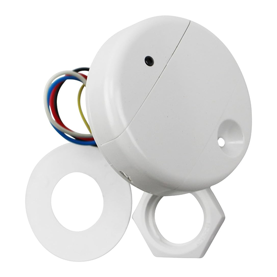
Indoor Contact Input Photosensor
The photosensor has been provided with a threaded mounting post
and washer and lock nut to allow connection through a ceiling tile.
The mounting post may be removed by squeezing it near the
base of the PPS-4. This allows it to be mounted using the two
screw holes under the cover. Use two #6 pan head screws that
are appropriately length for the mounting location. This type
of mounting may be used for sheetrock locations.
Window Application
When used in a window application, the PPS-4 should be located
within 12 feet of the window and away from any direct light from
controlled fixtures. Ideally, locating the photosensor between the
window and first row of fixtures is recommended. Rotate the PPS-4
so that the light sensor is nearest the window.
Skylight Application
There are two options for mounting a sensor that will be looking
at contributed light from a skylight. It is important that the sensor
be mounted such that it is not looking at direct sunlight as this will
cause the sensor to exceed the maximum of its range. To prevent
this, locate the sensor either on the South wall of the skylight well
looking North (sensor should be rotated so that the sensor's eye
is at the top) or mount on the ceiling next to the skylight looking
down at the floor (sensor should be rotated so that the sensor's
eye is closest to the skylight well).
Wiring Detail
INSTALLATION SHEET
Model#
PPS-4
Advertisement
Table of Contents

Related Manuals for Greengate PPS-4


Summary of Contents for Greengate PPS-4
- Page 1 The mounting post may be removed by squeezing it near the motion sensors for daylight harvesting. base of the PPS-4. This allows it to be mounted using the two screw holes under the cover. Use two #6 pan head screws that The operating range of the photosensor is 1 to 1400 foot- are appropriately length for the mounting location.
- Page 2 1000 feet. Wiring the PPS-4 to a Lighting Controller The PPS-4 photosensor wires to the low-voltage switch input channels on the lighting controller’s logic board. 1. Connect the Blue wire to the ON of the input channel. 2. Connect the Red wire to the +24VDC of the input channel.
- Page 3 Wiring the PPS-4 to a Greengate BAS Sensor Alternatively, the PPS-4 photosensor may wire directly to a Green- gate Switchpack and BAS sensor to provide daylight harvesting capability in a motion sensor application. In this configuration, the BAS contacts are used for the photosensor wiring. When the pho- tosensor sees enough light, the lighting will turn off and remain off regardless of motion sensor activity.
- Page 4 Make note of the current light level. If the PPS-4 is wired to a lighting control panel, it is recommended 6. Press the menu button until the display is at the CTRL that the sensor be programmed into the lighting controller prior menu.
- Page 5 Sensor section for details on overriding the sensor. All products manufactured by Cooper Controls and identified with the Greengate brand are warranted to be free from defects in material and workmanship and shall conform to and perform in accordance with Seller’s written specifications for a period of : •...
Need help?
Do you have a question about the PPS-4 and is the answer not in the manual?
Questions and answers