Table of Contents
Advertisement
Quick Links
General Information
• Read all instructions on both sides of this sheet first
• For Use with Greengate Switchpacks & Systems Only
• Install in accordance with ALL local codes
• Do not run any Greengate Low Voltage Wiring in the
• For indoor use only
same conduit as power conductors
Specifications
Power Requirements:
Operating Environment:
Input:
• Temperature: 32° F – 104° F (0° C – 40° C)
• 10-30 VDC from Greengate Switchpack or Greengate
• Relative Humidity: up to 90% non-condensing
system. Maximum current needed is 25mA per sensor
Output:
• Open collector output to switch up to ten
Greengate Switchpacks.
• BAS with Isolated Form C Relay (-R model)
• Isolated Form C Relay Ratings: 1A 30 VDC/VAC
Description
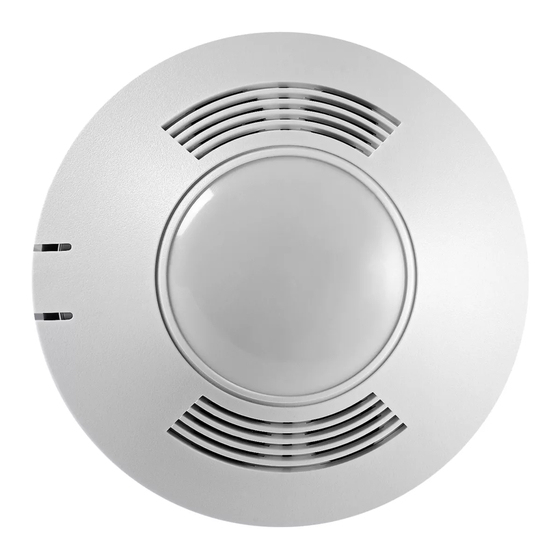
The OAC-DT Ceiling Mount Low Voltage Occupancy Sensor is a Passive Infrared (PIR) and Ultrasonic (US) motion
sensing lighting control, used for energy savings and convenience. PIR is used to turn the lights ON and then either
technology is used to keep the lights ON. When motion is detected, the blue wire is electronically connected to the
red wire, energizing the relay in the switchpack to turn on the load. If vacancy is detected, the blue wire is discon-
nected from the red, causing the relay to open turning OFF the load. The red lead is 10-30 VDC supply, the black
lead is common, and the blue is the relay control.
The sensor includes self-adaptive technology that continually adjusts to conditions by adjusting sensitivity and Time
Delay in real-time.
Coverage
20 ft
(6.096m)
12 ft
(3.65 m)
9 ft
(2.74 m)
0
9 ft
(2.74 m)
12 ft
(3.65 m)
20 ft
(6.096m)
8.5 ft
(2.59 m)
0
5 ft
10 ft
15 ft
23 ft
(1.52 m)
(3.05 m)
(4.57 m)
(7.01 m)
Minor Motion, IR
Maximum coverage area may
vary somewhat according to room
Major Motion, IR
shape and the presence of obstacles.
Minor Motion, Ultrasonic
The NEMA WD 7 Guide and robotic
method were utilized to verify
Major Motion, Ultrasonic
coverage patterns.
Cooper Controls
203 Cooper Circle, Peachtree City, GA 30269
800-553-3879
www.coopercontrol.com
Dual Technology Ceiling Mounted Low
Voltage Occupancy Sensor
Coverage
Location
The maximum coverage area may vary somewhat according to room shape and the presence of obstacles. Decrease
total coverage area by 15% for "soft" rooms (for example, heavy draperies or heavy carpeting). The sensor must have a
clear view of the area to be controlled. The sensor will not "see" through glass. Mounting height should not exceed 12
feet. Optimum mounting height is 8 to 10 feet. Mount the sensor so the grilles face the open portion of the room and are
not facing a nearby wall, door, window, or other obstructing object. Avoid pointing into hallways. Mounting at fixture
height is most effective. *To prevent false activation, the sensor should be mounted away from the air supply duct a min-
imum of 4 to 6 feet.
30 ft
0.762 m
OAC-DT-1000 & OAC-DT-2000
OAC-STEM Threaded Rod
Ultrasonic
Activated
15 ft
0.381 m
30 ft
30 ft
0.762 m
0.762 m
OAC-DT-0501
(sold separately)
Installation Instructions
Model # OAC-DT-0501
Model # OAC-DT-0501-R
Model # OAC-DT-1000
Model # OAC-DT-1000-R
Model # OAC-DT-2000
Model # OAC-DT-2000-R
Wiring
CAUTION: Before installing or performing any service on a Greengate system, the power MUST be turned OFF at
the branch circuit breaker. According to NEC 240-83(d), if the branch circuit breaker is used as the main switch
for a fluorescent lighting circuit, the circuit breaker should be marked "SWD". All installations should be in com-
pliance with the National Electric Code and all state and local codes.
NOTE REGARDING COMPACT FLUORESCENT LAMPS: The life of some compact fluorescent lamps (CFLs) is shortened
by frequent automatic or manual switching. Check with CFL and ballast manufacturer to determine the effects of cycling.
1. Make sure power is turned OFF at the branch circuit breaker.
2. Wire units as shown in wiring diagrams per applicable voltage requirements. (Use twist-on wire connectors
for all connections) CAP ALL UNUSED WIRE LEADS.
3. Mount unit to ceiling, junction box, or round fixture with raceway.
4. Turn power back ON at the branch circuit breaker and wait 2 minutes for the unit to stabilize.
5. Make necessary adjustments. (See Checkout and Adjustments section)
One Sensor, One Switchpack
Hot
Line
Neutral
**Use black lead for 120 VAC
Use orange lead for 277 VAC
Cap unused lead.
SWITCH-
Red (15 VDC)
PACK
Blue
Blue (Control)
Black (Common)
Red
To additional sensors
Blue
Maximum of 5 sensors
Black
per switchpack
To additional switchpacks
Maximum of 10 switchpacks
per sensor
Manual or Automatic-On Control of
Two Standard Switchpacks
Hot
Line
Neutral
**Use black lead for 120 VAC
Use orange lead for 277 VAC
Cap unused lead.
SWITCH-
Red (15 VDC)
PACK
Blue
Blue (Control)
Black (Common)
Red
Blue
Black
Brown
Yellow
**Use black lead for 120 VAC
Purple
Use orange lead for 277 VAC
Gray
Cap unused lead.
Orange
White/Brown
Red (15 VDC)
Manual Mode Operation:
Switches are required to
Blue (Control)
turn corresponding loads ON.
Black (Common)
Lights turn OFF when sensor
times out or with the
switch.
Model GMDS - Load 2
Automatic Mode Operation:
(Normally Open
Sensor turns ON both
Momentary Switch)
switchpacks. Switches can
be used to turn lights ON
or OFF.
Model GMDS - Load 1
(Normally Open
If daylight sensor is
Momentary Switch)
enabled and light level is
above setpoint, switchpack
connected to yellow lead
will not turn ON.
Recommended Wire:
18-3 AWG Stranded Wire
non/shielded.
Load
SENSOR WIRE LEAD LEGEND
Black
(Common)
Red
(10-30 VDC)
Blue
(Control - Occupancy)
Yellow
(Control - Occupancy and Daylight)
Brown
(Switch-Blue Lead Control)
Brown/White (Switch-Yellow Lead Control)
Sensor's Isolated Relay
Orange
(Normally Open)
Gray
(Common)
Purple
(Normally Closed)
Load 1
Hot
Line
Neutral
Load 2
SWITCH-
PACK
Blue
Advertisement
Table of Contents

Related Manuals for Greengate OAC-DT-0501


Summary of Contents for Greengate OAC-DT-0501
- Page 1 Coverage Wiring CAUTION: Before installing or performing any service on a Greengate system, the power MUST be turned OFF at • Read all instructions on both sides of this sheet first • For Use with Greengate Switchpacks & Systems Only the branch circuit breaker.
- Page 2 In Manual-ON Mode, the optional momentary low voltage switch(es) is required to turn the load(s) ON. Once activated All products manufactured by Cooper Controls and identified with the Greengate brand are warranted to be free from defects in Adjustments Section) the sensor will maintain the lights ON until motion ceases and the Time Delay expires.
Need help?
Do you have a question about the OAC-DT-0501 and is the answer not in the manual?
Questions and answers