Table of Contents
Advertisement
Quick Links
Advertisement
Table of Contents

Subscribe to Our Youtube Channel
Related Manuals for THORLABS MLDEVAL


Summary of Contents for THORLABS MLDEVAL
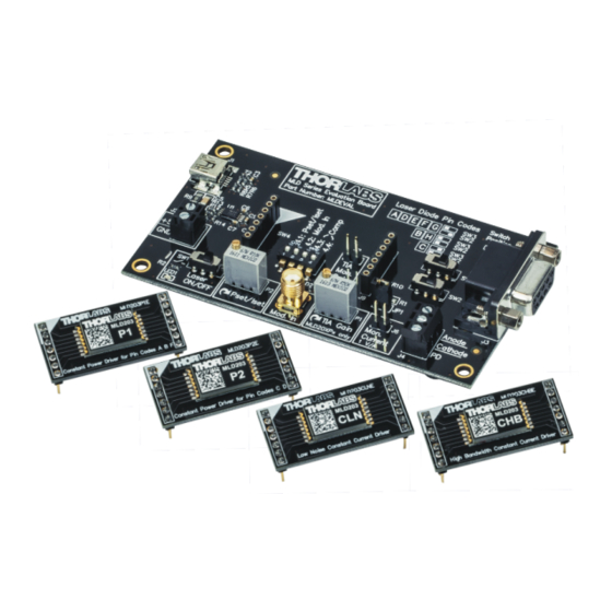
- Page 1 Miniature Laser Driver Evaluation Board MLDEVAL User Manual 2021...
- Page 2 Version: Date: 19-Feb-2021 Copyright © 2021 Thorlabs...
-
Page 3: Table Of Contents
4.1 External Power Control 5 Operating a MLD203CxxE Module (CC) 5.1 External Current Control 6 Appendix 6.1 Technical Data 6.2 Schematic Diagrams 6.3 Dimensions 6.4 Documentation Reference 6.5 Tutorial 6.6 Warranty 6.7 Copyright and Exclusion of Reliability 6.8 Thorlabs Worldwide Contacts... - Page 4 Paragraphs preceded by this symbol explain hazards that could damage the instrument and the connected equipment or may cause loss of data. Note This manual also contains "NOTES" and "HINTS" written in this form. Please read this advice carefully! © 2021 Thorlabs...
-
Page 5: General Information
ESD Notice The MLDEVAL is power input has an isolated ground potential. For this reason, the used power supply must have a galvanic isolation between its GND output and the neutral / protective con- ductor of the power line. Four rubber feet on the PCB's bottom provide an electrical isolation to the work bench. -
Page 6: Ordering Codes And Accessories
· SR9x ESD Protection and Strain Relief Cables · SR9x-DB9 ESD Protection and Strain Relief Cables with DB9 connector Note Adapter PCBs are not included with the MLDEVAL. They need to be ordered separately! Please visit https://www.thorlabs.com/newgrouppage9.cfm?objectgroup_id=2710 for closer in- formation about SR9x and SR9x-DB9 cables with respect to laser diode pin codes. -
Page 7: Operating Elements
Mod. In SMA connector for external control voltage input P1 TIA Gain Potentiometer to set the TIA gain (monitor current limit) - only MLD203P1 / MLD203P2 J6 Mon. Current Connector to monitor the laser diode current. Conversion coefficient 1 V/A © 2021 Thorlabs... -
Page 8: Power Supply Connection
In the case that both the USB and the external power supply is connected to the MLDEVAL, it will automatically use the external power supply. The protection circuit features also a reverse voltage protection and a reverse current blocking. -
Page 9: Preparation
For CC mode, select the appropriate adapter PCB depending on your preferences regard- ing low noise (MLD203CLNE) or high modulation bandwidth (MLD203CHBE). All pin codes are supported. Then continue with Operating a MLD203CxxE Module (CC) on page © 2021 Thorlabs... -
Page 10: Operating A Mld203Pxe Module (Cp)
Connect the DSUB plug to the DB9 output connector (7). 8. Make sure that SW1 (9) is set to off. 9. Connect the power supply (external 5 V DC via or a USB power) to the MLDEVAL. © 2021 Thorlabs... -
Page 11: External Power Control
7. Make sure that SW1 (9) is set to off. 8. Connect the power supply (external 5 V DC via or a USB power) to the MLDEVAL. 9. Set SW1 (9) to ON. The green LED1 next to SW1 lights up. -
Page 12: Operating A Mld203Cxxe Module (Cc)
5. Make sure that SW1 (9) is set to off. 6. Connect the power supply (external 5 V DC via or a USB power) to the MLDEVAL. 7. The laser diode current can be monitored at the J6 Mon. Current Connector (13) by meas- uring the voltage at this connector. -
Page 13: External Current Control
5. Make sure that SW1 (9) is set to off. 6. Connect the power supply (external 5 V DC via or a USB power) to the MLDEVAL. 7. The laser diode current can be monitored at the J6 Mon. Current Connector (13) by meas- uring the voltage at this connector. -
Page 14: Appendix
-40 to 70 °C 105.8 mm × 56.0 mm × 14.1 mm Dimensions (W x H x D) Weight 0.04 kg ) non-condensing All technical data are valid at 23 ± 5°C and 45 ± 15% rel. humidity (non condensing) © 2021 Thorlabs... -
Page 15: Schematic Diagrams
For better readability in this manual, the schematic diagram is split in functional blocks. MLD203xxxE interface (see Operating Elements on page , items 3, 4, 5, 10, 11, 12 and 13) Screw terminal for laser diode connection (see Operating Elements on page , item 8) © 2021 Thorlabs... - Page 16 MLDEVAL DB9 terminal for laser diode connection (see Operating Elements on page , items 6 and USB power supply input (see Operating Elements on page , item 1) © 2021 Thorlabs...
- Page 17 6 Appendix External 5 V DC power supply with reverse voltage protection (see Operating Elements on page , item 2) © 2021 Thorlabs...
-
Page 18: Dimensions
MLDEVAL 6.3 Dimensions Dimensions MLDEVAL Board © 2021 Thorlabs... - Page 19 6 Appendix Dimensions MLD203P1E Module © 2021 Thorlabs...
- Page 20 MLDEVAL Dimensions MLD203P2E Module © 2021 Thorlabs...
- Page 21 6 Appendix Dimensions MLD203CHBE Module © 2021 Thorlabs...
- Page 22 MLDEVAL Dimensions MLD203CLNE Module © 2021 Thorlabs...
-
Page 23: Documentation Reference
Click to appropriate link to download the data sheet: MLD203P1 Constant Power Miniature Laser Diode Driver MLD203P2 Constant Power Miniature Laser Diode Driver MLD203CHB Constant Current High Bandwidth Miniature Laser Diode Driver MLD203CLN Constant Current Low Noise Miniature Laser Diode Driver © 2021 Thorlabs... -
Page 24: Tutorial
Laser diodes come with different connection schemes of laser and monitor diode, particularly with respect to the common pin. For this reason, Thorlabs offers two types of CP miniature laser drivers, depending on the pin code of the laser (see... -
Page 25: Warranty
Thorlabs warrants material and production of the MLDEVAL for a period of 24 months starting with the date of shipment. During this warranty period Thorlabs will see to defaults by repair or by exchange if these are entitled to warranty. -
Page 26: Thorlabs Worldwide Contacts
Contact Thorlabs for more information. Waste treat- ment is your own responsibility. “End of life” units must be returned to Thorlabs or handed to a company specializing in waste recovery. Do not dispose of the unit in a litter bin or at a public waste disposal site.
Need help?
Do you have a question about the MLDEVAL and is the answer not in the manual?
Questions and answers