Table of Contents

Related Manuals for Lincoln industrial CENTRO-MATIC A Series


Summary of Contents for Lincoln industrial CENTRO-MATIC A Series
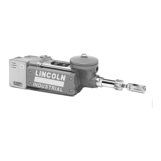
- Page 1 CENTRO-MATIC ® Air Operated Single Stroke Pumps with Controls, Air Return Models for Fluids: 85430, 85431, 85432, 85433 Models for Grease: 85434, 85435, 85436, 85437 Series “A” - 264 - C8 August 1998 Form 418803 Section Page 4.1A-68020-A98...
-
Page 2: General Description
CENTRO-MATIC ® Table of Contents Safety Description General Description Electrical Warning! hazard- ous electrical Warning! hazard- Appropriate Use • • • Product Specification Control Output Reservoir Capacity Air Pressure Air Consumption Operating Model Pump Ratio Voltage Current Per Stroke Pint Cu. -
Page 3: Timer Mode
CENTRO-MATIC ® Control Operation (See Illustration 1 for Controller Mode Mode Switch Controller Operating Control Descriptions) Timer Timer Mode • T • Mode Switch Timer • Units On Time • Alarm L.E.D. Alarm Manual Lube Manual Lube Manual Lube Manual Lube Illustration 1 Illustration 2 Illustration 1... - Page 4 CENTRO-MATIC ® Wiring Diagram Wiring Diagram Pump Operation (See Illustration 2) Electrical Connections (See Wiring Diagram) Optional Devices Pressure Switch Installing the Pump (See Illustrations 3, 4 & 5) Controller • Page Number - 4 4.1A-68020-A98 Form 418803...
- Page 5 CENTRO-MATIC ® Setting the Timer/Controller Low Level Switch Warning! • Timer Controller Memory, Units, • Mode of Operation On Time (Off Time Alarm Contacts • Maintenance & Repair Do Not Exceed Ratings. General Maintenance Putting Pump into Operation Filling Fluid Reservoirs In Case of Trouble Filling Models 85432 and 85433 (See Trouble Shooting Chart Page 12)
- Page 6 CENTRO-MATIC ® Grease Reservoir Service (See Illustration 11) Solenoid Valve Replacement (See Illustration 8) Warning! Warning! Oil Reservoir Service (See Illustration 9) Warning! Page Number - 6 4.1A-68020-A98 Form 418803...
- Page 7 CENTRO-MATIC ® Outlet Check and Vent Assembly Service (See Illustration 7) Reservoir Service Pump Tube and Air Cylinder Service (See Illustration 8) Warning! Reservoir Service Timer/Controller Replacement Solenoid Valve Replacement Oil or Grease Reservoir Service Outlet Check and Vent Assembly Service 4.1A-68020-A98 Page Number - 7...
- Page 8 CENTRO-MATIC ® Illustration 3 Models 85430 and 85431 (Dimensions are in Inches [mm]) 12.84 9.96 [253] [326] 8.36 2.13 Illustration 3 [213] [54] 2.37 3.00 [60] [76] 5.34 6.52 [136] [166] 22.81 [579] 15.49 [394] 18.11 [460] 2X .65 2.61 2.00 [66] [51]...
- Page 9 CENTRO-MATIC ® Illustration 5 Models 85434, 85435, 85436 and 85437 11.86 12.84 [301] [326] 8.38 2.13 [213] [54] 2.37 3.00 [60] [76] 5.34 6.52 [136] [166] Illustration 5 24.70 [627] 15.49 [394] 18.11 [460] 2x.65 [17] 2.61 2.00 [66] 2.12 [51.7] [54] 2.58...
- Page 10 CENTRO-MATIC ® Illustration 8 All Models Illustration 10 Illustration 11 Illustration 9 Models 85432, 85433 Models 85434, 85435, 85436 &85437 Models 85430, 85431 Page Number - 10 4.1A-68020-A98 Form 418803...
-
Page 11: Repair Parts List
CENTRO-MATIC ® Repair Parts List Models Item Quan Description 85430 85431 85432 85433 85434 85435 85436 85437 Outlet Adapter 13064 13064 Gasket Pump Tube 13063 13063 O-Ring (Nitrile) O-Ring (Nitrile) Bushing & Plunger Ass’y 92079 91403 92303 Gasket (Copper) Washer 48217 48375 48487... - Page 12 CENTRO-MATIC ® Lube Systems without Alarm Monitoring Condition Possible Cause Corrective Action Pump does not operate. No air to pump. Turn on or connect air supply to pump. No electric power to pump. Turn on electric power to pump. “POWER” L.E.D. should light, “PUMP ON”...
Need help?
Do you have a question about the CENTRO-MATIC A Series and is the answer not in the manual?
Questions and answers