Lincoln industrial A Series Installation Manual
Hydraulically operated grease pump
Hide thumbs
Also See for A Series:
- Manual (12 pages) ,
- Instructions manual (9 pages) ,
- Quick start manual (8 pages)
Advertisement
Table of Contents
MAY - 98
HYDRAULICALLY OPERATED
POWER REQUIREMENTS:
RATIO(See Note in Fig. 2)
INPUT PRESSURE
INPUT FLOW @ 30 CYCLES PER MINUTE
MAXIMUM HYDRAULIC TEMP.
OUTPUT PRESSURE
OUTPUT FLOW @ 30 CYCLES PER MINUTE
AMBIENT TEMP.
SEALS
FILTRATION REQUIRED
DESCRIPTION
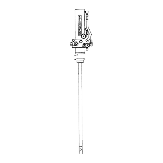
Model 84964 is a hydraulically
operated grease pump designed for
centralized lubrication systems on off-
road equipment which utilize 120VAC
power sources.
OWNER/OPERATOR
RESPONSIBILITY
It is the owner/operator responsibility to
properly use and maintain this
equipment.
The instructions and warnings
contained in this manual shall be read
and understood by the owner/operator
prior to operating this equipment.
If an owner/operator does not
understand English, the contents of
this manual shall be explained in the
owner/operator native language to
assure the owner/operator
comprehends.
It is the owner/operator responsibility to
maintain the legibility of all warning
and instruction labels.
The owner/operator shall retain this
manual for future reference to
Important warnings, operating and
maintenance instructions.
One Lincoln Way
St. Louis, Missouri 63120-1578
(314) 679-4200
MODEL NO. 84964
GREASE PUMP-
SPECIFICATIONS
SV1 & SV2= .13 Amps @ 120VAC each
POLYURETHANE AND NITRILE
Failure to heed the following warnings
including misuse, over pressurizing,
modifying parts, using incompatible
chemicals and fluids, or using worn or
damaged parts, may result in
equipment damage and/or serious
injury.
• Do not exceed the stated maximum
working pressure of the pump or of
the lowest rated component in your
system.
• Do not alter or modify any part of this
equipment.
• Do not attempt to repair or
disassemble the equipment while
the system is pressurized.
• Make sure all fluid connections are
securely tightened before using this
equipment.
• Always read and follow the fluid
manufacturer' s recommendations
regarding fluid compatibility, and the
use of protective clothing and
equipment.
• Check all equipment regularly and
repair or replace worn or damaged
parts immediately.
Copyright 1998
Printed in U.S.A.
SERIES "A"
16:1
300-3000 P.S.I.
1.0 G.P.M.
210° F
7500 P.S.I. MAX.
11 CU. IN./MIN.
-40° TO +135° F
10 MICRON
- C8
Section
- 268
Page
FORM 402821
Advertisement
Table of Contents

Subscribe to Our Youtube Channel
Related Manuals for Lincoln industrial A Series


Summary of Contents for Lincoln industrial A Series
- Page 1 MODEL NO. 84964 HYDRAULICALLY OPERATED GREASE PUMP- SERIES "A" SPECIFICATIONS POWER REQUIREMENTS: SV1 & SV2= .13 Amps @ 120VAC each RATIO(See Note in Fig. 2) 16:1 INPUT PRESSURE 300-3000 P.S.I. INPUT FLOW @ 30 CYCLES PER MINUTE 1.0 G.P.M. MAXIMUM HYDRAULIC TEMP. 210°...
-
Page 2: Safety Instructions
11 3/16" 3" (300 MM) (76 MM) NOTE: 242207 Pressure Reducing Valve is factory set @ 300 PSI. Turn clockwise to increase 15-1/4" pressure. (387 MM) NOTE: For Centro-matic applications, connect port to top of Vent Valve with high pressure 1/4" hose. For 1/4"... -
Page 4: Troubleshooting
TROUBLESHOOTING If the following procedures do not correct the problem, contact a factory authorized service center. When submitting equipment to be repaired, be sure to state the nature of the problem and indicate if a repair cost estimate is required. PROBLEMS CYLINDER PRESSURE GAUGE DOES NOT REGISTER PRESSURE. - Page 5 DISASSEMBLY N. Extend plunger rod (11723) out of Refer to SERVICE PARTS for part bushing extension and unscrew numbers and location. Bleed all priming plunger (11724) to allow pressure from hydraulic and grease removal of priming check parts and lines before disassembling pumps. plunger rod (11723).
- Page 6 TORQUE SPECIFICATIONS 10 - 15 FT. LBS. (14 - 20 NM) 80 FT. LBS. (108 NM) 30 FT. LBS. (41 NM) 90 FT. LBS. (122 NM) 45 IN. LBS. (5 NM) 100 FT. LBS. (135 NM) Page 6 Form 402821...
-
Page 7: Service Parts
SERVICE PARTS PART QTY. DESCRIPTION PART QTY. DESCRIPTION 11329 Piston Bolt 50178 Bolt 11340 Pistion Rod 50771 Bolt 11344 Plunger adapter 57027 Ball stop 11345 Coupling nut 61273 Bushing extension 11346 Coupling stud 61285 Pump tube 11349 Pistion rod connector +66010 Ball +11702... - Page 8 RETAIN THIS INFORMATION FOR FUTURE REFERENCE When ordering replacement parts, list: Part Number, Description, Model Number and Series Letter. LINCOLN provides a Distributor Network that stocks equipment and replacement parts. Page 8 Form 402821...
Need help?
Do you have a question about the A Series and is the answer not in the manual?
Questions and answers