Table of Contents
Advertisement
Quick Links
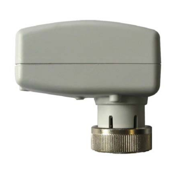
VA-747x Series
Electronic Terminal Unit Valve Actuator
Installation Guide
M30 x 1.5
Figure 1: Dimensions in mm
Figure 4: Cover for jumper selection
(a).
ELECTRONIC BOARD
M
Figure 5: VA-7470-1001
Floating Model Wiring
Figure 2: Mounting actuator on the valve
Max 90°
OK
Figure 3: Mounting Positions
M
24 V~
common
Figure 6: VA-7472-1001 and VA-7472-9001
Johnson Controls
All marks herein are the marks of their respective owners. © 2010 Johnson Controls, Inc.
Part No. 14-88400-17 Rev. A
Issued 04 2010
Max 90°
OK
NO!
ELECTRONIC BOARD
com
0...10V input
control signal
common
24 V~
Proportional Models Wirings
Building Efficiency
Headquarters: Milwaukee, Wisconsin, USA
Branch Offices: Principal Cities World-wide
®
is registered trademark of Johnson Controls, Inc.
www.johnsoncontrols.com
Advertisement
Table of Contents

Related Manuals for Johnson Controls VA-747 Series


Summary of Contents for Johnson Controls VA-747 Series
- Page 1 Floating Model Wiring Building Efficiency Headquarters: Milwaukee, Wisconsin, USA Branch Offices: Principal Cities World-wide ® Johnson Controls is registered trademark of Johnson Controls, Inc. All marks herein are the marks of their respective owners. © 2010 Johnson Controls, Inc. www.johnsoncontrols.com...
- Page 2 English This document is subject to change without notice READ THIS INSTRUCTION SHEET AND THE SAFETY WARNINGS CAREFULLY BEFORE INSTALLING AND SAVE IT FOR FUTURE USE General Features Figure 5: VA-7470-1001 Floating Model Wiring Figure 6: VA-7472-1001 and VA-7472-9001 Proportional Models Wirings The VA-747x Series provides floating or proportional control in HVAC applications.
Need help?
Do you have a question about the VA-747 Series and is the answer not in the manual?
Questions and answers