Advertisement
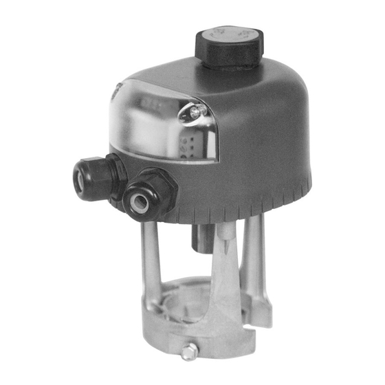
VA-7700■Series
Electric■Valve■Actuators
The VA-77xx Series synchronous motor driven actuator, for
valves in heating, ventilation and air conditioning applications,
is available for floating (3-point) control or proportional control
with 0-10 V position feedback signal.
It provides a stroke capability of 8 mm to a maximum 20 mm.
This compact, non spring return actuator has a 500 N nominal
force and responds to a variety of input signals.
The actuator can be combined with VG7000, VG9000
and VGS8... valves in accordance with the maximum
close-off pressure ratings specified (see pertinent valve
product bulletins).
They can be ordered as a separate unit or as a factory fitted
valve / actuator combination.
■ ■ Self■adjusting■proportional■actuators■
Easy, quick and precise commissioning servicing
■ ■ Column■of■5■Light■Emitting■Diodes
Allows easy visualisation of actuator stroke position and of the actuator status
■ ■ Optional■models■with■mechanical■manual■override
Allows manual positioning independent of the power supply
■ ■ Manual■contact■micro■switch■on■all■models■with■manual■override
Signals actuator mode status (automatic or manual) to external supervisory system.
■ ■ IP54■protection■class
Allows installation in a wide range of environments
■ ■ Unique■"C"■shaped■yoke■design
Allows lateral mounting of the actuator reducing the vertical space over the valve needed for
installation.
■ ■ Positioner■with■selectable■starting■point■and■span,■direct■and■reverse■action■modes
Enables sequence control
■ ■ Magnetic■clutch
Provides constant output force for close-off of valves, and protects motor in stall conditions
■ "Control-Signal■failure■"■stem■to■pre-determined■position
Actuator pre-set position after a control signal failure (extended/retracted), is selectable in-situ
PB_VA-7700_Electricl Valve Actuators_02 2011
Advertisement
Table of Contents

Subscribe to Our Youtube Channel
Related Manuals for Johnson Controls VA-77 Series


Summary of Contents for Johnson Controls VA-77 Series
- Page 1 PB_VA-7700_Electricl Valve Actuators_02 2011 VA-7700■Series Electric■Valve■Actuators The VA-77xx Series synchronous motor driven actuator, for valves in heating, ventilation and air conditioning applications, is available for floating (3-point) control or proportional control with 0-10 V position feedback signal. It provides a stroke capability of 8 mm to a maximum 20 mm. This compact, non spring return actuator has a 500 N nominal force and responds to a variety of input signals.
-
Page 2: Ordering Codes
PB_VA-7700_Electricl Valve Actuators_02 2011 Ordering■Codes For■VG7000■and■VG9000■Series■Valves: For■VGS8…■Series■Valves: Device■code Power■supply Manual■override Device■code Power■supply Manual■override Floating■models■(3-point) Floating■models■(3-point) VA-7700-1001 24 VAC None VA-7700-8201 24 VAC None VA-7700-1003 230 VAC None VA-7700-8203 230 VAC None VA-7740-1001 24 VAC Mechanical VA-7740-8201 24 VAC Mechanical VA-7740-1003 230 VAC Mechanical VA-7740-8203... -
Page 3: Operation
PB_VA-7700_Electricl Valve Actuators_02 2011 Operation Control■signal■failure■pre-set■position■ Floating■models ■ (not functional with 0…20 mA control selected) Connections Actuator■Stem A control-signal failure on proportional models will cause the Extends actuator to automatically move the stem to a (via DIP-switches) Retracts pre-selected position (100% extended or 100% retracted). Auto■Calibration■procedure■with■standard■... - Page 4 PB_VA-7700_Electricl Valve Actuators_02 2011 Auto-calibration■procedure■for■freely■defined■ Position■feedback control■signal■ranges■ The position feedback signal is for monitoring the actuator stroke position. It feeds information internally to the positioner and a Non standard control signals for example 2…8 VDC are applied 0-10 VDC signal can supply an external supervisory system. by setting the DIP switches 3 and 4 (see paragraph "DIP switch settings").
-
Page 5: Dip■Switches■Settings
PB_VA-7700_Electricl Valve Actuators_02 2011 DIP■switches■settings■ (Proportional models only) The DIP switches are accessed by removing the transparent cover. 1, 2: Default■setting■from■factory: Control signal Type All switches in left hand position 0...10 Voltage control 0...5 VDC 0...10 VDC 3, 4, 5: 5. -
Page 6: Standard■Operating■Mode
PB_VA-7700_Electricl Valve Actuators_02 2011 Standard■operating■mode Fault■mode The LED display indicates the actuator stem position. If the actuator enters fault mode, the LED will flash as shown. The LED stops flashing when the position corresponding to the The indication is general and is displayed when: control signal has been reached. - Page 7 PB_VA-7700_Electricl Valve Actuators_02 2011 Applications:■Parallel■and■sequential■operation Actuators■without■built-in■positioner■for■ Actuators■with■built-in■positioner■for■ controllers■with■PAT■(Positioning■Adjusting■ controllers■with■0…10V■output■in■parallel■ Time)■output■in■parallel■operation operation Although synchronous motors have the same running speed Com 0...10V 24VAC (rate of travel), deviation in travel between motors can accumulate during starts and stops because of varying loads. 0...10 V 0...10 V This deviation depends on the number of on/off cycles.
-
Page 8: Mounting Instructions
PB_VA-7700_Electricl Valve Actuators_02 2011 Mounting■instructions Wiring■instructions When mounting the actuator on a valve, please follow the • All wiring must be in accordance with local regulations instructions below: and national electrical codes and should be carried out by authorised personnel only. •... -
Page 9: Wiring Diagrams
PB_VA-7700_Electricl Valve Actuators_02 2011 Wiring■Diagrams■ (Models with mechanical manual override) WARNING:■■ Equipment■Damage■Hazard • On■24■V■models■with■manual■override,■it■is■not■ permitted■to■connect■voltages■greater■than■■ 24■V■to■terminals■10,■11,■and■12 VA-7740-xx01■-■Floating■models,■24■VAC■supply VA-7740-xx03■-■Floating■models,■230■VAC■supply VA-7746-xx01■-■Proportional■models,■24■VAC■supply... - Page 10 PB_VA-7700_Electricl Valve Actuators_02 2011 Wiring■Diagrams (Models without mechanical manual override) VA-7700-xx01■-■Floating■models,■24■VAC■supply VA-7700-xx03■-■■Floating■models,■230■VAC■supply VA-7706-xx01■-■Proportional■models,■24■VAC■supply...
- Page 11 PB_VA-7700_Electricl Valve Actuators_02 2011 Dimensions■(in mm) VA-77xx-10xx 25 mm VA-770x: actuators without manual override A■ 80 mm VA-774x: actuators with manual override ■■■■■■■■■■■■■■■■■■■VA-77xx-82xx...
-
Page 12: Technical Specifications
Metasys® and Johnson Controls® are registered trademarks of Johnson Controls, Inc. All other marks herein are the marks of their respective owners. © Copyright 2011 Johnson Controls, Inc. All rights reserved. Any unauthorized use or copying is strictly prohibited. www.johnsoncontrols.com...
Need help?
Do you have a question about the VA-77 Series and is the answer not in the manual?
Questions and answers