Table of Contents
Advertisement
Quick Links
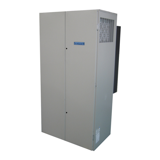
Scholar III™
Heat Pumps & Air Conditioners
(CSI 15740)
MAINTENANCE &
SERVICE
Model VAIA
2, 2.5, 3, 3.5, 4 & 5
Tons
CAUTION!!
Read all instructions before use.
Retain this manual for future
reference. This equipment should
be installed and serviced only by a
trained professional HVAC service
person.
D u e t o c o n t i n u o u s p r o d u c t
improvement, use only the current
issue of this manual. The latest
version can be downloaded from the
Scholar III™
Marvair website - www.marvair.com.
R
N
Unitary Air-Conditioners AC
Unitary Air-Source Heat Pumps HP
Manufactured By:
Marvair
Division of AIRXCEL
, Inc.
®
®
P.O. Box 400 • Cordele, Georgia 31010
156 Seedling Drive • Cordele, Georgia 31015
(229) 273-3636 • Fax (229) 273-5154
E-mail: marvairtech@airxcel.com • Internet: www.marvair.com
SIII M&S 8/09-1
Advertisement
Table of Contents

Related Manuals for Airxcel Marvair Scholar III VAIA Series


Summary of Contents for Airxcel Marvair Scholar III VAIA Series
- Page 1 Unitary Air-Source Heat Pumps HP Manufactured By: Marvair Division of AIRXCEL , Inc. ® ® P.O. Box 400 • Cordele, Georgia 31010 156 Seedling Drive • Cordele, Georgia 31015 (229) 273-3636 • Fax (229) 273-5154 E-mail: marvairtech@airxcel.com • Internet: www.marvair.com SIII M&S 8/09-1...
-
Page 2: Table Of Contents
SECTION 15700 HEaTINg, VENTIlaTINg aNd aIr CONdITIONINg EquIpmENT maINTENaNCE & SErVICE maNual fOr SCHOlar III HEaT pump & aIr CONdITIONEr, mOdEl VaIa (CSI 15740) TablE Of CONTENTS Chapter Description Page General Description ..............3 1.2 Model Identification ..............4 Start-up Instructions ..............5 Ventilation System Calibration ............7 Electrical ..................9 Maintenance ................14 Function &... -
Page 3: General Description
SECTION 15700 HEaTINg, VENTIlaTINg aNd aIr CONdITIONINg EquIpmENT The purpose of this manual is to provide instructions for maintenance and service for the Marvair Scholar III™ series of heat pumps and air conditioners. In addition to this manual, ® there are other pieces of literature available from Marvair. The Engineering and Design Manual details the design and selection of HVAC systems using the Scholar III series. -
Page 4: Model Identification
reheat is available with motorized fresh air, PowerVent and GreenWheel ventilation ® systems. Marvair recommends that for optimum performance, hot gas reheat be used in ® conjunction with the GreenWheel heat recovery ventilator. When used with other ® ventilation options, hot gas reheat may not maintain satisfactory control of the humidity in the classroom over all outdoor conditions. -
Page 5: Start-Up Instructions
2.1 STarT-up prOCEdurE A. This start-up procedure applies to Scholar III™ models equipped with a remote (wall mounted) thermostat and electric supplemental heat. 1. Turn the disconnect in the Scholar III™ unit to “OFF” position and double check all electrical connections before applying power. 2. Check the voltage supply to the disconnect. If voltage readings are appropriate, proceed with start-up. (See Figure 2 for acceptable voltage ranges.) If voltage readings are not appropriate, check the power leads at the disconnect and the main breaker in the mechanical room. Take appropriate corrective action to supply sufficient voltage to the Scholar III™ disconnect. - Page 6 Now slowly raise the cooling set point up toward room temperature until the pump compressor and outdoor blower motor turn off. This will be audible. The indoor blower will continue to run and turn off after 90 seconds. 5a. Heating (heat pump version only) a.
-
Page 7: Ventilation System Calibration
2.2 VENTIlaTION SySTEm CalIbraTION The ventilation system requires calibration to ensure the appropriate amount of fresh air is delivered to the classroom. Refer to the appropriate following ventilation system and use the instructions to calibrate the system for correct air delivery. A. - Page 8 Follow the directions in Figure 4 to ensure the proper air flow rate setting. After calibrating the ventilation system, replace the lower front cabinet panel. Figure 3. Manual Fresh Air System Calibration Procedure Inside the lower section, locate the circular calibration plates as noted in the drawing (“A”...
-
Page 9: Electrical
3.1 ElECTrICal Scholar III heat pumps and air conditioners are built in a wide variety of configurations and options. The illustrations of the control center and the electrical schematics shown here are typi- cal, but probably are not identical to your units. Please refer to the electrical schematic in each unit for the specific con struction of that unit. - Page 10 Figure 7a. Typical Wiring Schematic for Heat Pump Model VAIA, Single Phase Power Scholar III (M&S) 8/09-1 15700 - 10 HVAC Equipment...
- Page 11 Figure 7b. Typical Wiring Schematic for Air Conditioner Model VAIA, Single Phase Power Scholar III (M&S) 8/09-1 15700 - 11 HVAC Equipment...
- Page 12 Figure 8a. Typical Wiring Schematic for Heat Pump Model VAIA, Three Phase Power Scholar III (M&S) 8/09-1 15700 - 12 HVAC Equipment...
- Page 13 Figure 9a. Remote Wall Mounted Thermostat Wiring Detail Thermostat Field Supplied Seven (7) Conductor, Color Coded Thermostat Cable GeoScholar Heat Pumps Note: A/C’s do not have “O”. THE INTErNal TraNSfOrmEr IS NOT dESIgNEd TO pOWEr OTHEr EXTErNal dEVICES. Figure 9b. Humidity Controller Wiring Detail Thermostat Field Supplied Seven (7) Conductor, Color Coded...
-
Page 14: Maintenance
4.1 maINTENaNCE WarNINg bEfOrE pErfOrmINg maINTENaNCE ON THE SCHOlar III™, SWITCH ElECTrIC pOWEr Off aT THE dISCONNECT lOCaTEd bEHINd THE rIgHT frONT dOOr. faIlurE TO dO THIS COuld rESulT IN prOpErTy damagE, bOdIly INjury Or dEaTH. A. Air filters on the Scholar III™ model VAIA require scheduled inspection and maintenance. - Page 15 rotation is not an issue with single-phase compressors since they will always start and run in the proper direction. However, three phase compressors will rotate in either direction depending upon phasing of power. Since there is a 50-50 chance of connecting power in such a way as to cause rotation in the reverse direction, it is imperative to confirm that the compressor is rotating in the proper direction at the initial field start-up of the system. Verification of proper rotation is made by observing that the suction pressure drops and the discharge pressure rises when...
- Page 16 C. Outdoor air mover. The outdoor air mover is an axial fan with an asynchronous external rotor motor on the 2, 2½, 3, & 3½ heat pumps and all air conditioners. Scholar III heat pumps, models VAIA & VAISA 48 & 60 use two blowers with electronically commutated motors (ECM). One of the blowers operates a full speed anytime the compressor is on.
- Page 17 D. Indoor/Outdoor Coils. The coils are constructed of lanced, aluminum fins mechanically bonded to rifled, seamless copper tubes. E. filter drier - The filter drier performs two functions in the refrigerant circuit. First, it removes foreign particulate matter, e.g. dirt, scale, solder particles from the refrigerant to protect the compressor and other components in the refrigerant system with small openings or close tolerances. Second, it absorbs any moisture in the refrigerant with desiccant granules.
- Page 18 H. reversing Valve. The reversing valve reverses the refrigerant’s direction of flow in a heat pump, allowing the heat pump to switch from cooling to heating or heating to cooling. I. Exhaust air Ventilation blower is used to exhaust classroom in the GreenWheel ERV and Power Vent ventilation options. The blower can exhaust up to 450 CFM of air from the classroom. In the standard configuration, both the exhaust and the intake ventilation blowers are controlled by a single speed controller. This speed controller permits the motor speed to be adjusted for the correct cfm of ventilation...
- Page 19 N. programmable logic Controller (plC) microprocessor. The Scholar III heat pump uses a factory installed PLC microprocessor to control the operation, the safety switches and function options. LED’s show operational status and provide assistance with diagnosis if troubleshooting is ever required. Various control functions are field selectable. The PLC is also capable of communicating to other Scholar III unit PLC’s to allow run time leveling and does not require additional equipment installed in the Scholar III unit.
- Page 20 On the right side of the PLC there is a small door. Behind the door is a three position micro switch and two control adjustments- an anti short cycle timer and a defrost timer. Each control can be adjusted by turning the knob with a small flat head screwdriver. The indicator on the knob is the gap between the two protrusions with the hollow centers on the knob. (See drawing below). For both control timers, turning the knob clockwise increases the time period. NOTE: Scholar III air conditioners do not have the defrost function. The micro switch has three positions – ruN, TErm & STOp.
- Page 21 plC Inputs The PLC inputs are powered only by 24 VAC. The thermostat inputs are: g - Blower signal from thermostat • y - Compressor • W2 - Second stage heat (heat pump function only) • O - Reversing valve (energized for cooling) (heat pump function only) •...
- Page 22 plC Outputs An output is a signal from the PLC to the Scholar III™ heat pump or thermostat. The first four outputs, from left to right, are connected to a 230 VAC supply and thus provide 230 VAC when energized. These outputs are: • Oam - Outdoor Air Motor (Fresh air motor for the GreenWheel ERV)
- Page 23 Operation guide Cooling Mode During normal operation of the system, the thermostat calls for cooling by turning on the G, Y and O inputs to the system. This request will be indicated on the G, Y and O indicators at the bottom of the unit. If the compressor has been off for a least the amount of time interval set on the ASCT, the Compressor Contactor (CC), Indoor Blower (Ibm), Reversing Valve (RVS) and the Outdoor Fan Motor (OFM) LED’s should be on. This indicates that the controller is sending an output to turn those devices on. Heating Mode When the thermostat calls for first stage heating, it turns on the G and Y inputs.
- Page 24 minutes, the system will revert back to normal heating mode. By having a maximum time for the Defrost Cycle to operate, the system will not go into Defrost and remain in Defrost mode if a Defrost Switch malfunctions. If the Electric Heat During Defrost (EHDD) function has been selected, the Heat Contactor (HTR) will come on to supply supplemental heat during the Defrost Cycle.
- Page 25 P. Standard Ventilation Control. The motorized fresh air damper with powerVent and greenWheel ErV ventilation options are equipped with a fresh ® air fan speed control. The fresh air fan speed control operates both the ventilation intake and exhaust blowers together. Optional Ventilation Controls. The unit control system is factory wired to energize the ventilation package anytime the indoor fan/blower is energized. If additional control of the ventilation package is desired, it may be accomplished by the following: The controls contractor must remove the factory installed jumper between...
-
Page 26: Troubleshooting
6.1 TrOublESHOOTINg In diagnosing common faults in the heat pump system, develop a logical thought pattern as used by experienced technicians. The charts which follow are not intended to be an answer to all problems but only to guide the technician’s thinking. Through a series of yes and no answers, follow the logical path to a likely conclusion. A novice technician should use these charts like a road map. Remember that the chart should clarify a logical path to the problem’s solutions. Electrical Checks flow Chart unit running? Thermostat Problem? - Page 27 Cooling mechanical Checks flow Chart unit running? Pressure Problems? High Head low Head low Suction pressure pressure pressure Dirty Outdoor Coil Low on Charge Dirty Filters Inoperative Outdoor Low Ambient Dirty Indoor Coil Temperature Overcharge Inoperative Inadequate Indoor Air Compressor Valves Flow Recirculation of Outdoor Check Valve Inoperative Indoor Outdoor Air...
- Page 28 Heating mechanical Checks flow Chart unit running? Pressure Problems? High Head low Head low Suction pressure pressure pressure Dirty Filters Low on Charge Dirty Outdoor Coil Dirty Indoor Coil Low Indoor Inadequate Air Flow Temperature Over Outdoor Coil Inoperative Indoor Closed Indoor Check Inoperative OD Fan Blower Valve Overcharge Inoperative Low on Charge...
- Page 29 Subcooling Calculation 1. Measure the liquid pressure at the liquid line service valve. 2. Convert the liquid line pressure to saturated temperature. See tables below. 3. Measure the liquid line temperature at the liquid line service valve. 4. Compare the liquid line temperature to the saturated temperature. 5.
- Page 30 Troubleshooting Chart WarNINg dISCONNECT all pOWEr TO uNIT bEfOrE SErVICINg. CONTaCTOr may brEaK ONly ONE SIdE. faIlurE TO SHuT Off pOWEr CaN CauSE ElECTrICal SHOCK rESulTINg IN pErSONal INjury Or dEaTH. problem/Symptom likely Cause(s) Correction Unit will not run. Power off or loose electrical Check for correct voltage at unit discon- connection.
- Page 31 Troubleshooting Chart (cont’d) problem/Symptom likely Cause(s) Correction Low head - high vapor Flow check piston size too large. Change to correct size piston. pressures. Defective compressor valves. Replace compressor. Incorrect capillary tubes. Replace coil assembly. Low vapor - cool com- Low indoor air flow. Increase speed of blower or reduce pressor - iced indoor coil.
- Page 32 Compressor Overheating (cont’d) problem/Symptom likely Cause(s) Correction High head pressure. Overcharge. Check system charge. Dirty heat pump coil. Clean coil. Faulty or wrong size heat pump Replace fan motor. fan motor. Faulty outdoor blower. Replace blower. Recirculation of air. Replace with correct rotation motor. Additional heat source.
- Page 33 Electrical (cont’d) problem/Symptom likely Cause(s) Correction No voltage on line side Blown fuses or tripped circuit breaker. Check for short in wiring or unit. of compressor contactor. Improper wiring. Recheck wiring diagram. Improper voltage. High voltage. Power supply problem. Low voltage. Power supply problem. Wiring undersized. Loose connections. Single phasing (3 phase). Check incoming power and fusing. Contamination Moisture.
- Page 34 flooding (cont’d) problem/Symptom likely Cause(s) Correction Poor system control Overcharge. Check system charge. using capillary tubes. High head pressures. Dirty heat pump. Restricted air flow. Recirculation of air. Evaporator air flow too low. Adjust air flow to 400 CFM/Ton. Thermostatic Expansion Valves High superheat, low Moisture freezing and blocking Recover charge, install filter drier, suction pressure. valve. evacuate system, recharge. Dirt or foreign material blocking Recover charge, install filter-drier, valve.
- Page 35 Thermostatic Expansion Valves (cont’d) problem/Symptom likely Cause(s) Correction Compressor flood back Any of the causes listed under Any of the solutions listed under upon start-up symptoms of problem 2. solutions of problem 2. Superheat is low to Unequal evaporator circuit Ensure air flow is equally distributed normal with low loading.
-
Page 36: Service
7.1 SErVICE a. Changing the return air filters Tools Required • Slotted screw driver or key for opening front doors There are two return filters in the upper (indoor) section of the unit. A filter is located behind each of the return grilles. To remove the filters, open both doors and slide the filters out as shown below. rETurN aIr fIlTErS b. Changing the Ventilation air filters Tools Required • Slotted screw driver The ventilation filter(s) are located in the left section of the bottom compartment behind a panel. Scholar III (M&S) 8/09-1 15700 - 36 HVAC Equipment... - Page 37 1. Remove the two screws at the top and bottom of each panel to access the filters. 2. Slide the filters out to inspect/replace. After inspecting/replacing of the filters, replace filter access panel. Scholar III (M&S) 8/09-1 15700 - 37 HVAC Equipment...
- Page 38 C. access to the Indoor Coils for Cleaning Tools Required • 5/16” Nut Driver 1. Remove the top cover – fifteen screws. 2. Remove the filters. 3. Carefully spray the coils with the cleaning solution. Use care NOT to spray the electrical connections for the indoor motor. Scholar III (M&S) 8/09-1 15700 - 38 HVAC Equipment...
- Page 39 d. access to Outdoor Coils for Cleaning Tools Required • 5/16” Nut Driver 1. Remove the two screws that hold the condensate line to the middle front door. Note: Do not remove or disconnect the condensate tubing. 2. Remove the eighteen screws that hold the door. 3.
- Page 40 4. With the door removed, carefully spray the coils with the cleaning solution. COIl COIl E. removal of fresh air Intake blower motor Tools Required • 5/16” Nut Driver • Slotted Screw Driver • Clippers to Cut Wire Tie 1. Remove the two screws that hold the blower in place. SCrEWS Scholar III (M&S) 8/09-1...
- Page 41 2. Remove the eight screws that hold the lower plenum front cover. 3. Cut tie wrap that hold wires. 4. Disconnect the four wires at the butt splice. 5. Slide the blower motor out. Scholar III (M&S) 8/09-1 15700 - 41 HVAC Equipment...
- Page 42 f. access to the greenWheel drive motor and the greenWheel and the damper motor for the “b” Ventilation Option, and access to 460v. transformer and to fresh air exhaust motor. Tools Required • 5/16” Nut Driver • 5/16” Socket Wrench or Open End Wrench • Clippers to Cut Wire Tie 1. Remove ventilation filters. 2. Remove ventilation fresh air intake blower motor. (See instructions for removing this blower/motor.) 3. Remove the filter cover holder – seven screws.
- Page 43 4. Remove the filter rack assembly – thirteen screws. 5. Remove the two GreenWheel dividers – one on the left and one on the right. Each divider has two screws. Scholar III (M&S) 8/09-1 15700 - 43 HVAC Equipment...
- Page 44 6. Disconnect wires to the GreenWheel drive motor or the damper motor. While lifting up on the horizontal divider panel that rests on the ventilation module, pull the ventilation module out of the unit.. Access to 460v. transformer and to fresh air exhaust motor is behind this panel.
- Page 45 g. removal of the Indoor blower motor Tools Required • 5/16” Nut Driver • Clippers to Cut Wire Tie 1. Remove the top cover – fifteen screws. 2. Disconnect the two electrical harnesses on the blower motor. Scholar III (M&S) 8/09-1 15700 - 45 HVAC Equipment...
- Page 46 3. Cut the tie wrap that holds the wires to the blower housing. 4. Remove the six screws – two on the left, two in the front and two on the right that hold the blower motor to the top panel. These screws penetrate the blower motor flange vertically into the top panel.
- Page 47 H. removal of the Outdoor fan motor assembly (2, 2-1/2, 3 & 3-1/2T units Only) Tools Required • 7/16” Socket • 5/16” Nut Driver 1. Remove the two screws that hold the condensate line to the middle front door. Note: Do not remove or disconnect the condensate tubing. 2.
- Page 48 3. Disconnect the flexible duct by removing the screws at the top and bottom of the duct. 4. Remove the six bolts that hold the fan motor assembly. It is necessary to hold the nut on the backside of the flange when unscrewing the bolts. BOLT Scholar III (M&S) 8/09-1 15700 - 48 HVAC Equipment...
- Page 49 5. Carefully rotate the fan motor assembly 90° and pull the assembly out of the machine. Use care not to damage the coil or a refrigerant line when removing the fan motor assembly. I. removal of the Outdoor fan motor assembly (4 & 5T units Only) Tools Required •...
- Page 50 Remove Three Screws on Each Side Electrical Plugs j. removal of the fresh air Exhaust fan motor Tools Required • 5/16” Nut Driver • No. 2 Phillips Head Screwdriver 1. Remove the 18 screws that hold the middle door. Scholar III (M&S) 8/09-1 15700 - 50 HVAC Equipment...
- Page 51 2. Remove the lower plenum front cover - eight screws. 3. Remove the lower plenum divider/access door – ten screws. 4. Remove yellow flexible duct. 5. Disconnect wires to the fan motor. 6. Remove fan motor – two Phillips head screws. Scholar III (M&S) 8/09-1 15700 - 51 HVAC Equipment...
- Page 52 K. access to Electrical box Tools Required • 5/16” Nut Driver 1. Remove the eight screws that hold the control box cover panel. location of major components 1. Compressor, reversing valve and coil, Schrader fittings and condensate drain hose. SCHRADER FITTINGS CoMPRESSoR REVERSING VAlVE CONDENSATE TUB- Scholar III (M&S) 8/09-1 15700 - 52 HVAC Equipment...
- Page 53 2. Outdoor Coil, Filter drier, High pressure switch, Loss of charge switch, Outdoor orifice, Defrost sensor, Flexible duct for ventilation air. HIGH PRESSURE SWITCH OUTDOOR ORIFICES LOSS OF CHARGE SWITCH VENTILATION DUCT DEFROST FILTER DRIER OUTDOOR SENSOR COIL 3. Indoor Coil, Indoor blower motor assembly and Thermal Expansion Valve. INDOOR COILS THERMAL EXPANSION VALVES INDOOR MOTOR ASSEMBLY Scholar III (M&S) 8/09-1 15700 - 53 HVAC Equipment...
- Page 54 4. Outdoor thermostat, reheat valve and solenoid coil for reheat valve. OUTDOOR THERMOSTAT REHEAT VALVE & SOLENOID VALVE Scholar III (M&S) 8/09-1 15700 - 54 HVAC Equipment...
-
Page 55: Filing A Service/Warranty Claim
8.1 prOCEdurE fOr fIlINg a WarraNTy ClaIm 156 Seedling Drive • Cordele, GA 31015 • P.O. Box 400 • Cordele, GA 31010-0400 Phone 800-841-7854 • 229-273-3636 • Fax 229-276-1479 • Svc Pager 800-204-8210 MARVAIR SERVICE REQUEST / PURCHASE ORDER FOR SERVICE DATE TIME TIME... -
Page 56: Warranty Statement
9.1 WarraNTy If any part of your Marvair® Air Conditioner, Heat Pump or Unit Ventilator fails because of a manufacturing defect within fifteen months from the date of original shipment from Marvair or within twelve months from the date of original start-up, whichever is the earlier date, Marvair will furnish without charge, EXW Cordele, Georgia, the required replacement part. Any transportation, related service labor, diagnosis calls, filter, driers, and refrigerant are not included. -
Page 57: Exploded Views And Parts List
10.1 parTS lIST Scholar III™ Heat Pump Parts List parTS VaIa24Hp VaIa30Hp VaIa36Hp VaIa40Hp VaIa48Hp VaIa60Hp 10333 (K5) 10298 10349 10352 10310 10313 Compressor 10327 10299 10350 10353 10311 10314 10328 10300 10351 10354 10312 10315 50280 50315 50321 50321 50327 50315 (2) Capacitor, Compressor (ufd/Volts) - Page 58 parTS VaIa24Hp VaIa30Hp VaIa36Hp VaIa40Hp VaIa48Hp VaIa60Hp Tubeaxial Fan, (EXM) (Ventilation options H, J) 30165 30165 30165 30165 30165 30165 Damper, Backdraft 01523 01523 01523 01523 01523 01523 Energy Recovery Wheel (Ventilation option H) 01226 01226 01226 01226 01226 01226 Motor, GreenWheel Drive (Ventilation option H) 40007 40007 40007 40007...
Need help?
Do you have a question about the Marvair Scholar III VAIA Series and is the answer not in the manual?
Questions and answers