Table of Contents
Advertisement
Quick Links
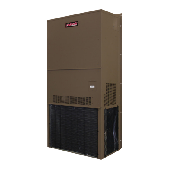
Installation & Operation Manual
1.5 - 4 Ton Vertical Wall-Mount Heat Pumps
EAA1020H • EAA1024H/2024H
EAA1030H/2030H • EAA1036H/2036H
EAA1042H/2042H • EAA1048H
This manual may include information for options and features which may not be
included on the unit being installed. Refer to the unit data label or Model Identification
to determine which features and options this unit is equipped with.
INSTALLER: Affix the instructions on the inside of the building adjacent to the thermostat.
END USER: Retain this manual for future reference.
A Division of the AIRXCEL
P.O. Box 400 • Cordele, Georgia 31010 • 156 Seedling Drive • Cordele, Georgia 31015
E-mail: marvairsales@airxcel.com • Internet: www.Marvair.com
The most current version of this manual can be found at www.Marvair.com.
MODELS:
IMPORTANT
Manufactured By:
(229) 273-3636 • Fax (229) 273-5154
Heat Pump Product Manual
Vertical Wall-Mount Heat Pumps
Commercial Group
®
Eubank Wall Mount Heat Pump I&O Manual 03/2021 Rev.3
Advertisement
Table of Contents
Troubleshooting

Related Manuals for Airxcel Eubank EAA1020H


Summary of Contents for Airxcel Eubank EAA1020H
- Page 1 INSTALLER: Affix the instructions on the inside of the building adjacent to the thermostat. END USER: Retain this manual for future reference. Manufactured By: A Division of the AIRXCEL Commercial Group ® P.O. Box 400 • Cordele, Georgia 31010 • 156 Seedling Drive • Cordele, Georgia 31015 (229) 273-3636 •...
- Page 2 Failure to comply could result in minor personal injury and/or property damage. Used to point out helpful suggestions that will result in improved installation, reliability IMPORTANT or operation. SPECIFICATIONS SUBJECT TO CHANGE WITHOUT NOTICE. © 03/2021 Airxcel Commercial Group Eubank Wall Mount Heat Pump I&O Manual 03/2021 Rev.3...
-
Page 3: Table Of Contents
WARNING • If the information in these instructions are not followed exactly, a fire may result causing property damage, personal injury or loss of life. • Read all instructions carefully prior to beginning the installation. Do not begin installation if you do not understand any of the instructions. •... - Page 4 Chapter 6 - Periodic Maintenance Requirements 6.1 Scheduled Maintenance ......................... 38 Chapter 7 - Warranty Information 7.1 Standard Product Warranty ........................39 Appendix A - Installation Instructions of Field Installed Electric Heat ............40 igures Figure 1 PC Control Board ........................13 Figure 2 Enthalpy Sensor Temperature Control Points .................
-
Page 5: General Description
Description and Specifications 1.1 General Description Eubank Wall Mount Heat Pumps are high efficiency, vertical wall mounted heat pumps that provide ® heating, cooling and ventilation for a wide range of applications. Nominal cooling capacities range from 20,000 to 48,000 BTUH. All models have EER's of 11.00 and feature quiet operation. -
Page 6: Model Identification
1.3 Model Identification Example E Position 10 11 12 13 14 15 16 17 18 19 20 21 22 23 24 25 26 27 28 29 30 E = Eubank Wall Mount D = Dry Bulb Sensor Unit Designation/Family S = Stock Unit E = Dry Bulb Sensor w/Dirty Filter 17 Indoor Air Quality Features G = Dirty Filter Sensor... -
Page 7: Air Flow, Weights And Filter Sizes
1.4 Air Flow, Weights and Filter Sizes. External Static Pressure (WET COIL) MODEL 0.10 0.20 0.25 0.30 0.40 0.50 EAA1020H/1024H EAA1030H 1100 1000 EAA1036H 1310 1220 1185 1150 1060 EAA1042H 1650 1585 1520 1450 1360 EAA1048H 1900 1830 1760 1700 1620 EAA1060H 1900... - Page 8 Ventilation Options Standard - Ventilation Configuration N: Manual damper capable of up to 15% of rated airflow of outside air; field adjustable, no pressure relief. Optional - Ventilation Configuration Y: Manual damper capable of 0 to 450 cfm (maximum of 40% of rated airflow) of outside air;...
-
Page 9: Controls - Standard - Pc Board
Quality Components The GreenWheel module consists of a desiccant wheel, two blowers and the drive motor and belt. The ® two blowers simultaneously pull fresh air from outside and exhaust air from the classroom through the rotating wheel. Two variable speed blowers ensure that up to 450 CFM of outside air can be brought into the room and the indoor air is properly exhausted. - Page 10 off (Post Purge). The user can select whether the compressor and electric heat operate simultaneously (the S-Circuit) and if electric heat operates during the defrost mode (EHDD). The board can control the operation of a two position motorized damper to provide fresh air for ventilation (DRO/DRC). In conjunction with an optional temperature sensor, the board will modulate the speed of the outdoor fan motor to allow cooling during low ambient temperatures.
- Page 11 Damper Relay (Damper Relay Open-DRO /Damper Relay Closed-DRC) The board has a two position, motorized fresh air damper (ventilation option “B”) from the “G” input when this option is selected. It is pin selectable using a jumper to select “Yes” to enable it. When “Yes” is selected, the control will energize the Damper Relay Open terminal when “G”...
- Page 12 High Pressure Switch (HPS) The high pressure switch is mounted on the compressor liquid line. The HPS terminals are on the high pressure switch input. This input monitors the status of the high pressure switch and determines when this fault condition is present. If the HPS is open on the initial “Y” call, the control board will not allow the compressor to operate.
-
Page 13: Pc Control Board
W2 The “W2” terminal is the electric heat input from the thermostat. When the control receives a call for “W2” from the thermostat, it will energize the EH terminal. When the S-Circuit is selected by placing the jumper in the Yes position, the control will not allow the compressor to run simultaneously with electric heat. -
Page 14: Options
1.7 Options Low Ambient Control The low ambient control permits mechanical cooling when outdoor ambient temperatures are low. The control uses a reverse-acting high pressure switch to cycle the condenser fan motor according to liquid refrigerant pressure conditions. Switch closure and fan operation occurs when the pressure reaches 400 PSIG. -
Page 15: Figure 2 Enthalpy Sensor Temperature Control Points
Economizer Changeover Control The enthalpy sensor responds to the total heat content of the outdoor air to provide changeover to outside air for free cooling. The change point is adjustable from 63°F @ 50% RH (full clockwise) to 73°F @ 50% RH (full counterclockwise). -
Page 16: Chapter 2 - Installation
Installation WARNING Failure to observe and follow Warnings and Cautions and these Instructions could result in death, bodily injury or property damage. Read this manual and follow its instructions and adhere to all Cautions and Warnings in the manual and on the Eubank unit. -
Page 17: Installation Materials
5. Airflow Requirements: Note the minimum CFM requirements (section 2.4). Keep duct lengths as short as possible. Do not obstruct airflow through the unit. Applications using duct work should be designed and installed in accordance with all applicable safety codes and standards. Eubank strongly recommends referring to the current edition of the National Fire ®... - Page 18 Standard Kit Components 1. One 12 Ga. “L”-shaped bottom bracket Accessories: The package may include other factory-supplied items (optional ) listed on this and the following page: PART # DESCRIPTION 50107 Digital thermostat. 2 stage heat, 2 stage cool. 7 day programmable. Fan switch: Auto & On. Auto-change over.
-
Page 19: Porting And Duct Work
(10) 3/8" mounting bolts or lag screws for side brackets and anchors, if required for side brackets. (20) 3/8" washers (10) 3/8" hex nuts 3/8" x 2-1/2" lag screws for bottom bracket Silicone Sealer to seal around cracks and openings •... -
Page 20: Fresh Air Hood Adjustment
Ducting Extensions should be cut flush with the inside wall for applications without duct work. Applications using duct work should be designed and installed in accordance with all applicable safety codes and standards. Eubank strongly recommends referring to the current edition of the National Fire ®... -
Page 21: Mounting The Unit
2. All heat pump models have built-in mounting flanges. See Figure 6. 3. Refer to Figure 6. Attach the bottom support bracket to the wall using appropriate 3/8" diameter hardware. For example, on wooden structures, use 3/8 x 2-1/2 inch all-thread lag screws. The screws must penetrate the center of the wall stud. -
Page 22: Electrical Connections
9. Check the fit of each sleeve to its mating flange for possible air leaks. Apply silicone sealer to close any gaps. Install the air return and supply grilles. 10. To minimize sound transmission, a latex based, insulating foam seal may be applied between the duct extensions and the frame for the wall openings. - Page 23 always start and run in the proper direction. However, three phase compressors will rotate in either direction depending upon phasing of power. Since there is a 50-50 chance of connecting power in such a way as to cause rotation in the reverse direction, it is imperative to confirm that the compressor is rotating in the proper direction at the initial field start-up of the system.
-
Page 24: Figure 5A Humidity Control Wiring Detail
Thermostat Field Supplied Seven (7) Conductor, Color Coded 18 Gauge Thermostat Cable Humidity Controller Figure 5a - Humidity Control Wiring Detail - Heat Pumps Figure 5b - Thermostat Connection Diagram Eubank Wall Mount Heat Pump I&O Manual 03/2021 Rev.3... -
Page 25: Chapter 3 - Start-Up
Start-Up Important: If your heat pump unit has a crankcase heater be sure that the crankcase heater has been energized for at least 24 hours prior to start-up of the unit. Double check all electrical connections before applying power. Various thermostats can be used to control the heat pump. The thermostat may have a fan switch with an Automatic and On positions, a system switch with Heat, Cool, and Off positions, and an emergency heat position with lights. -
Page 26: Check-Out Of Heating Cycle
sensors must be "tricked". When outdoor ambient conditions are higher than the control setting, a component aerosol cooler may be sprayed directly into the enthalpy sensor to simulate low enthalpy conditions, causing the economizer damper to open. Alternately, when outdoor conditions are lower than the set point, a source of heat such as a hair dryer can be directed on the air temperature sensor to simulate warmer conditions, which will bring on mechanical cooling and start the compressor. -
Page 27: Figure 6 Temperature Sensor Wires - Modulating Hgr Valve
(temperature). Airxcel Commercial Group recommends 70ºF and no lower than 68ºF and no higher than 78ºF. Allow the refrigerant system to stabilize for at least five minutes and adjust the temperature as desired. -
Page 28: Ventilation System Set Up
3.4 Ventilation System Set-Up: Manual Fresh Air System (Configuration N). This is the standard ventilation system in Eubank heat pumps. Fresh air ventilation by means of a damper can provide up to 15% of rated air flow of outside air. The damper has four positions corresponding to 0, 5, 10 and 15% of rated air flow of outside air. The damper only opens when the indoor fan is operating. -
Page 29: Figure 9 Damper Air Path
Figure 9 - Damper Air Path b. "A" is the quantity of outside air expressed as a percentage of "C". For example, if the supply air is 1,220 CFM and 300 CFM of outside air is required, "A" is 25% (300 CFM/1,220 CFM). Measure the temperature of the outside air. -
Page 30: Chapter 4 - Troubleshooting
b. For units with the optional variable fan speed controller for the GreenWheel ERV exhaust blower, first ® measure the air being introduced into the classroom using best industry standards and practices. Adjust the speed of the intake air GreenWheel ERV blower until the required outside air is being brought into the classroom. -
Page 31: Failure Symptoms Guide
4.2 Failure Symptoms Guide PROBLEM/SYMPTOM LIKELY CAUSE(S) CORRECTION A. Unit does not run. 1. Power supply problem. 1. Check power supply for adequate phase and voltage. Check wiring to unit and external breakers or fuses. NOTE: An internal anti-short-cycle timer will prevent the unit 2. -
Page 32: Compressor Troubleshooting
4.3 Compressor Troubleshooting Obtain the heat pump's model number and serial number, the compressor's model number and contact Airxcel Commercial Group for compressor specifications. It is important to rule out other component failures before condemning the compressor. The following electrical tests will aid diagnosis on single phase units: 1. -
Page 33: Electric Heat Control
4.4 Electric Heat Controls Figure 10 - Typical Configuration for Single Element Heater The electric heater assembly can have up to three individual heating elements. Each individual heating element is protected against overheating by its own dual function thermal cut-out switch. Additionally, a separate single function thermal cut-out switch protects the entire heater assembly. -
Page 34: Chapter 5 - Electrical Schematics
Electrical Schematics 5.1 Electrical Schematics The compressor and condenser fan are energized with a contactor controlled by a 24 VAC pilot signal. The condenser (outside fan) motor is energized by the same contactor. However, the motor is cycled on and off by the low ambient control (see low ambient control 1.5). Note: Only on heat pumps equipped with an economizer. -
Page 35: Figure 11A Typical 1Ø Electrical Schematic Diagram Heat Pump With Manual Outside Air Damper
Figure 11a - Typical 1ø Electrical Schematic Diagram Heat Pump (Models EAA) with Manual Outside Air Damper Eubank Wall Mount Heat Pump I&O Manual 03/2021 Rev.3... -
Page 36: Figure 11B Typical 208/230V. 3Ø Heat Pump Electrical Schematic Diagram
Figure 11b - Typical 208/230v. 3ø Electrical Schematic Diagram Heat Pump (Models EAA) Eubank Wall Mount Heat Pump I&O Manual 03/2021 Rev.3... -
Page 37: Figure 11C Typical 460V. 3Ø Heat Pump Electrical Schematic Diagram, With Pc Control Board
Figure 11c, Typical 460v. 3ø Electrical Schematic Diagram Heat Pumps, Models EAA, with the PC Control Board Eubank Wall Mount Heat Pump I&O Manual 03/2021 Rev.3... -
Page 38: Scheduled Maintenance
Maintenance 6.1 Scheduled Maintenance Eubank, Inc. strongly recommends that the heat pump be serviced a minimum of twice a year – once prior to the heating season and once prior to the cooling season. At this time the filters, evaporator coil, condenser coil, the cabinet, and condensate drains should be serviced as described below. -
Page 39: Chapter 7 - Warranty Information 7.1 Standard Product Warranty
Warranty 7.1 Marvair, Inc. Limited Product Warranty Marvair Inc., warrants its products to be free from defects in materials and workmanship under normal use to the original purchaser for the period of time in the table below. If any part of your product fails within 12 months from start-up, or 18 months from shipment from the factory, whichever comes first, Marvair, Inc. -
Page 40: Appendix A - Installation Instructions Of Field Installed Electric Heat
APPENDIX A: Installation Instructions for Field Installed Electric Heat WARNING FIRE HAZARD Improper adjustment, alteration, service, maintenance or installation could cause serious injury, death and/or property damage. Installation or repairs made by unqualified persons could result in hazards to you and others. - Page 41 WARNING ELECTRICAL SHOCK HAZARD Failure to follow safety warnings exactly could result in serious injury, death, and/or property damage. Turn off electrical power at fuse box or service panel BEFORE making any electrical connections and ensure a proper ground connection is made before connecting line voltage.
- Page 42 Eubank Wall Mount Heat Pump I&O Manual 03/2021 Rev.3...
- Page 43 APPENDIX B: Heat Pump Start-Up - Commissioning Checklist Please complete the information on this form and email to MarvairCustServ@airxcel.com. Date: _____/_____/_______ Owner & Location Equipment Owner: ___________________________________________________________________ Address: __________________________________________________________________ City: __________________________________________________________________ State:_______, Zip:____________ Installing Contractor Company: _______________________________Installer: ____________________________ Address: __________________________________________________________________...
- Page 44 Check Incoming Power at Terminal Block and verify Proper Voltage and Balance BEFORE STARTING UNIT. ❒ 208/230V 1 Phase 60 Hz. ❒ 208/230V 3 Phase 60 Hz. ❒ 460V 3 Phase 60 Hz. ❒ 380V 3 Phase 50Hz. ❒ 575 3 Phase 60 Hz. ❒...
- Page 45 9 Is the indoor blower motor (IBM) On? (if IBM fails to come on, Check Phase Monitor) ❒Yes ❒No 9 Is the Compressor On? (if Compressor fails to come on, Check Phase Monitor) .....❒Yes ❒No 9 Is the Condenser Fan (CFM) On? (Ambient conditions may be delay CFM) ....❒Yes ❒No 9 Is incoming power properly Phased? (YES! If “Green LED”...
- Page 46 Cooling (Check and Record Readings) After about 10 minutes of operating in the cooling mode, check and record the following data points. Inside Temperature (IAT) ºF Outside Temperature (OAT) ºF Entering Condenser Air Temperature (Should be same temp as OAT) ºF Leaving Condenser Air Temperature (Acceptable Range 15º...
- Page 47 Electric Reheat Re-Start While the system is still operating in “Cooling Mode” from the previous test. Re-Start Dehumidification. Do Not change the Humidity Setpoint on the Humidistat. Simply adjust the cooling setpoint to approximately four degrees above the current indoor temperature. After the short delay, the unit will sequence on, start dehumidification.
- Page 48 Economizer Cooling Stop Adjust the cooling setpoint to approximately two degrees above the current indoor temperature. The unit will sequence off. 9 Is the Economizer Damper Closed? .................. ❒Yes ❒No 9 Is the indoor blower motor (IBM) Off? ................❒Yes ❒No Heating Mode (Mechanical Heating Heat Pump) Close the Compressor (Cooling) circuit breaker.
- Page 49 Mechanical Heat Lockout ODT (Electric Heat ONLY While the system is operating in “Mechanical Heating Mode”. Activate Mechanical Heat Lockout (ODT). * Your unit may be configured with an outdoor thermostat configured as “Auxiliary Heat”, “Mechanical Heat Lockout”, or No outdoor thermostat. * Do Not change the temperature setpoint on the thermostat / control.
- Page 50 Three Phase Units Heater kW = (HCAL1*L1&L2) + (HCAL2*L1&L3) + (HCAL3*L2&L3)/1000 = __________kW. Example: (HCAL1*L1&L2) + (HCAL2*L1&L3) + (HCAL3*L2&L3) 1000 Measured Voltage: L1&L2 = 241 Volts Measured Amperage: L1 = 8.28 Amps 1995.48 Measured Voltage: L1&L3 = 243 Volts Measured Amperage: L1 = 8.22 Amps 1997.46 Measured Voltage: L1&L2 = 235 Volts Measured Amperage: L1 = 8.57 Amps...
- Page 51 Notes: ____________________________________________________________________________________ ____________________________________________________________________________________ ____________________________________________________________________________________ ____________________________________________________________________________________ ____________________________________________________________________________________ ____________________________________________________________________________________ ____________________________________________________________________________________ ____________________________________________________________________________________ ____________________________________________________________________________________ ____________________________________________________________________________________ ____________________________________________________________________________________ ____________________________________________________________________________________ ____________________________________________________________________________________ ____________________________________________________________________________________ ____________________________________________________________________________________ ____________________________________________________________________________________ ____________________________________________________________________________________ ____________________________________________________________________________________ ____________________________________________________________________________________ ____________________________________________________________________________________ ____________________________________________________________________________________ ____________________________________________________________________________________ ____________________________________________________________________________________ ____________________________________________________________________________________ ____________________________________________________________________________________ Eubank Wall Mount Heat Pump I&O Manual 03/2021 Rev.3...
Need help?
Do you have a question about the Eubank EAA1020H and is the answer not in the manual?
Questions and answers