Table of Contents
Advertisement
Quick Links
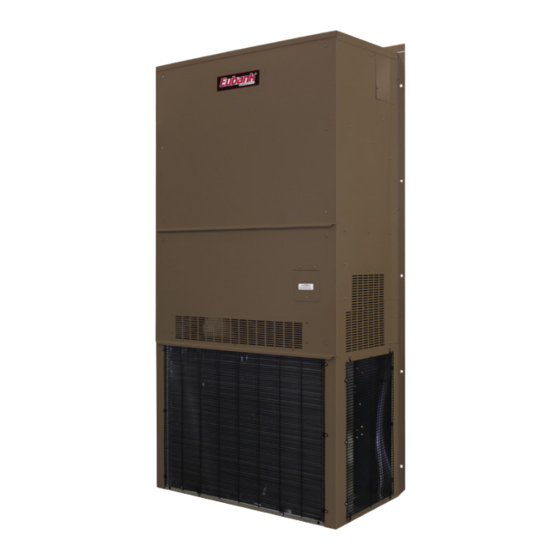
Installation & Operation Manual
11 EER Vertical Wall-Mount Heat Pumps
7AA1024H-1030H-1036H-1042H-1048H-1060H
(Single Stage Compressor)
7AA2024H-2030H-2036H-2042H-2048H-2060H
(2-Stage Compressor)
(Includes units with the GreenWheel
the GreenCube
This manual may include information for options and features which may not be
included on the unit being installed. Refer to the unit data label or Model Identification
to determine which features and options this unit is equipped with.
INSTALLER: Affix the instructions on the inside of the building adjacent to the thermostat.
END USER: Retain this manual for future reference.
A Division of the AIRXCEL
P.O. Box 400 • Cordele, Georgia 31010 • 156 Seedling Drive • Cordele, Georgia 31015
E-mail: eubanksales@airxcel.com • Internet: www.EubankWallmount.com
The most current version of this manual can be found at www.EubankWallmount.com.
MODELS:
®
ERV and Hot Gas Reheat)
®
IMPORTANT
Manufactured By:
(229) 273-3636 • Fax (229) 273-5154
Eubank 7AA1024H-1060H & 7AA2024H-2060H I&O Manual 03/2021 Rev.1
Heat Pump Product Manual
Vertical Wall-Mount Heat Pumps
with Front Control Box Panel
ERV,
Commercial Group
®
Advertisement
Table of Contents
Troubleshooting

Related Manuals for Airxcel Eubank 7AA1024H-1030H


Summary of Contents for Airxcel Eubank 7AA1024H-1030H
- Page 1 INSTALLER: Affix the instructions on the inside of the building adjacent to the thermostat. END USER: Retain this manual for future reference. Manufactured By: A Division of the AIRXCEL Commercial Group ® P.O. Box 400 • Cordele, Georgia 31010 • 156 Seedling Drive • Cordele, Georgia 31015 (229) 273-3636 •...
- Page 2 Failure to comply could result in minor personal injury and/or property damage. Used to point out helpful suggestions that will result in improved installation, reliability IMPORTANT or operation. SPECIFICATIONS SUBJECT TO CHANGE WITHOUT NOTICE. © 03/2021 Airxcel Commercial Group Eubank 7AA1024H-1060H & 7AA2024H-2060H I&O Manual 03/2021 Rev.1...
-
Page 3: Table Of Contents
WARNING • If the information in these instructions are not followed exactly, a fire may result causing property damage, personal injury or loss of life. • Read all instructions carefully prior to beginning the installation. Do not begin installation if you do not understand any of the instructions. •... - Page 4 Chapter 6 - Periodic Maintenance Requirements 6.1 Scheduled Maintenance ......................... 39 Chapter 7 - Warranty Information 7.1 Standard Product Warranty ........................40 Chapter 8 - Start-Up Check List 8.1 Start-Up & Commissioning Form ......................41 Appendix A - Installation Instructions of Field Installed Electric Heat ............45 igures Figure 1 PC Control Board ........................
-
Page 5: Chapter 1 Description & Specifications
Instructions for 7AA models with the GreenWheel® ERV and the GreenPac HGR are included in this manual. All Airxcel Commercial Group heat pumps are tested and certified for efficiency and capacity in accordance with the ANSI/AHRI (Air-Conditioning, Heating and Refrigeration Institute) Standard 390-2003 (Single Package Vertical Units). -
Page 6: Model Identification
1.2 Model Identification Example Position 10 11 12 13 14 15 16 17 18 19 20 21 22 23 24 25 26 27 28 29 30 D = Dry Bulb Sensor Unit Designation/Family 7 = Eubank Wall Mount E = Dry Bulb Sensor w/Dirty Filter Indoor Air Quality Energy Efficiency Ratio A = 11... -
Page 7: Serial Number Date Code
1.3 Serial Number Date Code 20 = 2020 01 = January 05 = May 09 = September 21 = 2021 02 = February 06 = June 10= October 22 = 2022 03= March 07 = July 11 = November 23 = 2023 04 = April 08 = August 12 = December... -
Page 8: General Operation
1.5 General Operation Refrigerant Cycle Eubank heat pumps use R-410A refrigerant in a conventional vapor-compression refrigeration cycle to transfer heat. In the cooling mode, a double blower assembly blows indoor air across the evaporator (indoor coil). Liquid refrigerant passing through the evaporator is boiled into gas by heat removed from the air. The warmed refrigerant gas enters the compressor where its temperature and pressure are increased. - Page 9 How It Works During the summer, cool dry air from the classroom is exhausted through the GreenWheel ERV to the ® outside. As the air passes through the rotating wheel, the desiccant becomes cooler and drier. Simultaneously, hot humid air is being pulled across the rotating wheel. The cool, dry desiccant absorbs moisture and heat from the incoming air.
-
Page 10: Controls - Standard - Pc Board
Economizer Operation - Cooling Cycle (Economizer-equipped modes only) The economizer is a regulated damper system with controls. The damper regulates the circulation of outside air into the enclosure (when the outdoor air conditions are suitable) to reduce the need for me- chanical cooling, save energy, and extend compressor life. - Page 11 Functions Lockout Protection If either of the fault conditions (LPS or HPS) occurs twice within one hour, the control board will enter into and indicate the lockout mode. In the lockout mode, the compressor is turned off. If there is a call for indoor air flow “G”, the blower remains energized, the alarm output is energized and the red LED will blink to indicate which fault has occurred.
- Page 12 to open. When the “G” signal is not present, the control will energize the Damper Relay Closed terminal to close the damper. When “No” is selected, this feature is disabled. The factory setting for the damper relay option is “No”. Defrost Mode The board has an integral defrost cycle that will be initiated by the Defrost Sensor (DS).
- Page 13 the compressor off, register the first HPS fault, and initiate the 3 minute anti-short cycle timer. If two HPS faults occur within a one hour period, the control will enter a HPS lockout condition and energize the alarm contacts. The RED status LED will blink once to indicate this condition. The lockout condition will only be reset by manually cycling power to the control to prevent destructive short cycling.
-
Page 14: Options
O The “O” terminal is the reversing valve input from the thermostat. When there is a 24 VAC signal present at the “O” terminal, the control will energize the reversing valve through the “RV” terminals. The control will also energize the “RV” terminals in heat mode during a defrost cycle. G The “G”... -
Page 15: Economizer
Hard Start Kit Used on single phase equipment to give the compressor higher starting torque under low voltage conditions. Field installed only. (Not generally recommended for use on scroll compressor.) Adjustable Outdoor Thermostat Will not allow electric resistance heat to be energized unless the outdoor temperature is below the desired set point. -
Page 16: Figure 2 Enthalpy Sensor Temperature Control Points
Controls The economizer is controlled by an enthalpy sensor or optional dry bulb sensor. Economizer Changeover Control The enthalpy sensor responds to the total heat content of the outdoor air to provide changeover to outside air for free cooling. The change point is adjustable from 63°F @ 50% RH (full clockwise) to 73°F @ 50% RH (full counterclockwise). -
Page 17: Chapter 2 Installation
Chapter 2 Installation WARNING Failure to observe and follow Warnings and Cautions and these Instructions could result in death, bodily injury or property damage. Read this manual and follow its instructions and adhere to all Cautions and Warnings in the manual and on the Eubank unit. -
Page 18: Table 4 Minimum Clearances
5. Airflow Requirements: Note the minimum CFM requirements (section 2.4). Keep duct lengths as short as possible. Do not obstruct airflow through the unit. Applications using duct work should be designed and installed in accordance with all applicable safety codes and standards. Eubank strongly recommends referring to the current edition of the National Fire ®... -
Page 19: Installation Materials
2.3 Installation Materials Installation Kits Eubank Heat Pumps have built-in mounting flanges that function as side brackets. All models require and are shipped with a bottom mounting bracket. On units with the "N" ventilation option, there is a fresh air hood factory installed behind the lower front panel. -
Page 20: Porting And Duct Work
Additional Items Needed: Additional hardware and miscellaneous supplies (not furnished by Eubank ) are needed for installation. ® For example, the list below contains approximate quantities of items typically needed for mounting a unit on a wood frame wall structure with standard full length mounting bracket or flanges. Concrete or fiberglass structures have different requirements. -
Page 21: Fresh Air Hood Adjustment
Minimum Airflow Requirements WARNING The duct system must be engineered to assure sufficient air flow through the Heat Pump, even under adverse conditions such as dirty filters, etc. Proper engineering will insure longevity and maximum performance from the Heat Pump unit. Ducting Extensions should be cut flush with the inside wall for applications without duct work. -
Page 22: Bracket Installation
2.6 Bottom Bracket Installation 1. Remove and discard the 4 x 4 shipping boards attached to the base of the unit. 2. All heat pump models have built-in mounting flanges. See Figure 6. 3. Refer to Figure 6. Attach the bottom support bracket to the wall using appropriate 3/8" diameter hardware. -
Page 23: Electrical Connections
inch clearance is required around the duct extensions. The duct extensions must be constructed of galvanized steel with a minimum thickness of .019” as per the NFPA standards 90A & 90B. 9. Check the fit of each sleeve to its mating flange for possible air leaks. Apply silicone sealer to close any gaps. - Page 24 3. Scroll compressors, like several other types of compressors, will only compress in one rotational direction. The direction of rotation is not an issue with single-phase compressors since they will always start and run in the proper direction. However, three phase compressors will rotate in either direction depending upon phasing of power.
-
Page 25: Figure 5A Humidity Control Wiring Detail
Figure 5a - Humidity Control Wiring Detail - Heat Pumps Figure 5b - Thermostat Connection Diagram Eubank 7AA1024H-1060H & 7AA2024H-2060H I&O Manual 03/2021 Rev.1... -
Page 26: Chapter 3 Start Up
Chapter 3 Start Up Important: If your heat pump unit has a crankcase heater be sure that the crankcase heater has been energized for at least 24 hours prior to start-up of the unit. Double check all electrical connections before applying power. -
Page 27: Check-Out Of Heating Cycle
sensors must be "tricked". When outdoor ambient conditions are higher than the control setting, a component aerosol cooler may be sprayed directly into the enthalpy sensor to simulate low enthalpy conditions, causing the economizer damper to open. Alternately, when outdoor conditions are lower than the set point, a source of heat such as a hair dryer can be directed on the air temperature sensor to simulate warmer conditions, which will bring on mechanical cooling and start the compressor. -
Page 28: Figure 6 Temperature Sensor Wires - Modulating Hgr Valve
(temperature). Airxcel Commercial Group recommends 70ºF and no lower than 68ºF and no higher than 78ºF. Allow the refrigerant system to stabilize for at least five minutes and adjust the temperature as desired. -
Page 29: Ventilation System Set Up
3.4 Ventilation System Set-Up: Manual Fresh Air System (Configuration N). This is the standard ventilation system in Eubank 7AA heat pumps. Fresh air ventilation by means of a damper can provide up to 15% of rated air flow of outside air. The damper has four positions corresponding to 0, 5, 10 and 15% of rated air flow of outside air. -
Page 30: Figure 9 Damper Air Path
Figure 9 - Damper Air Path b. "A" is the quantity of outside air expressed as a percentage of "C". For example, if the supply air is 1,220 CFM and 300 CFM of outside air is required, "A" is 25% (300 CFM/1,220 CFM). Measure the temperature of the outside air. - Page 31 b. For units with the optional variable fan speed controller for the GreenWheel ERV exhaust blower, first ® measure the air being introduced into the classroom using best industry standards and practices. Adjust the speed of the intake air GreenWheel ERV blower until the required outside air is being brought into the classroom.
-
Page 32: Chapter 4 Troubleshooting
Chapter 4 Troubleshooting 4.1 Overview A comprehensive understanding of the operation of the Eubank Heat Pump is a prerequisite to troubleshooting. Please read the Chapter 1 for basic information about the unit. Eubank Heat Pumps are thoroughly tested before they are shipped from the factory. However, it is possible ®... -
Page 33: Failure Symptoms Guide
4.2 Failure Symptoms Guide PROBLEM/SYMPTOM LIKELY CAUSE(S) CORRECTION A. Unit does not run. 1. Power supply problem. 1. Check power supply for adequate phase and voltage. Check wiring to unit and external breakers or fuses. NOTE: An internal anti-short-cycle 2. Tripped internal disconnect. 2. -
Page 34: Compressor Troubleshooting
4.3 Compressor Troubleshooting Obtain the heat pump's model number and serial number, the compressor's model number and contact Airxcel Commercial Group for compressor specifications. It is important to rule out other component failures before condemning the compressor. The following electrical tests will aid diagnosis on single phase 7AA units: 1. - Page 35 The dual function thermal cut-out switch (P/N 70006) is composed of two independent line voltage snap-disc temperature switches mounted in a single enclosure. One of these switches is an automatic reset device which cycles off at approximately 145°F and back on at approximately 115°F. Should this switch fail to open, the second switch will open the circuit if the temperature continues to increase.
-
Page 36: Chapter 5 - Electrical Schematics
Chapter 5 Electrical Schematics 5.1 Electrical Schematics The compressor and condenser fan are energized with a contactor controlled by a 24 VAC pilot signal. The condenser (outside fan) motor is energized by the same contactor. However, the motor is cycled on and off by the low ambient control (see low ambient control 1.5). -
Page 37: Figure 11A Typical 1Ø Electrical Schematic Diagram Heat Pump With Manual Outside Air Damper
Figure 11a - Typical Electrical Schematic Diagram Heat Pump Models with Manual Outside Air Damper Eubank 7AA1024H-1060H & 7AA2024H-2060H I&O Manual 03/2021 Rev.1... -
Page 38: Figure 11B Typical 208/230V. 3Ø Electrical Schematic Diagram Heat Pump
Figure 11b - Typical Electrical Schematic Diagram Heat Pump Models with Economizer Eubank 7AA1024H-1060H & 7AA2024H-2060H I&O Manual 03/2021 Rev.1... -
Page 39: Scheduled Maintenance
Chapter 6 Maintenance 6.1 Scheduled Maintenance Airxcel Commercial Group strongly recommends that the heat pump be serviced a minimum of twice a year – once prior to the heating season and once prior to the cooling season. At this time the filters, evaporator coil, condenser coil, the cabinet, and condensate drains should be serviced as described below. -
Page 40: Chapter 7 - Warranty Information
Chapter 7 Warranty Marvair, Inc. Limited Product Warranty Marvair Inc., warrants its products to be free from defects in materials and workmanship under normal use to the original purchaser for the period of time in the table below. If any part of your product fails within 12 months from start-up, or 18 months from shipment from the factory, whichever comes first, Marvair, Inc. -
Page 41: Chapter 8 Start-Up Check List
Chapter 8 Start-Up Check List Start-Up & Commissioning Form Please complete the information on this form and return to Eubank by mail or fax. The mailing address and fax number can be found at the end of the form. A. Equipment Information Date: ________________Equipment Owner _______________________________________ Installing Company: _____________________________Installer: ____________________ Address: _______________________________________State _______________________... - Page 42 Refrigerant Piping If leaks are found, report any leaks to ICE Warranty Service Dept. C. Check Rated Voltage at Terminal Block for Imbalance before starting of Unit. ❒208/230V 1 Phase ❒208/230V 3 Phase ❒460V 3 Phase ❒380V 3 Phase 50Hz. ❒575 3 Phase 60 Hz.
- Page 43 D. Heating Mode Check & Record Readings Circuit 1 Circuit 2 (if applicable) Room Temperature ________ ________ Outside Temperature ________ ________ Evap. Entering Air DB Temp ________ ________ Evap. Entering Air WB Temp ________ ________ Evap. Leaving Air DB Temp ________ ________ Evap.
- Page 44 After 10 minutes of compressor operation, record the following: Circuit 1 Circuit 2 (if applicable) Room Temperature ________ ________ Outside Temperature ________ ________ Suction Pressure ________ ________ Suction Line Temperature ________ ________ Discharge Pressure ________ ________ Discharge Line Temperature ________ ________ Entering Condenser Air ________...
-
Page 45: Appendix A - Installation Instructions Of Field Installed Electric Heat
APPENDIX A: Installation Instructions for Field Installed Electric Heat WARNING FIRE HAZARD Improper adjustment, alteration, service, maintenance or installation could cause serious injury, death and/or property damage. Installation or repairs made by unqualified persons could result in hazards to you and others. - Page 46 WARNING ELECTRICAL SHOCK HAZARD Failure to follow safety warnings exactly could result in serious injury, death, and/or property damage. Turn off electrical power at fuse box or service panel BEFORE making any electrical connections and ensure a proper ground connection is made before connecting line voltage.
- Page 47 Eubank 7AA1024H-1060H & 7AA2024H-2060H I&O Manual 03/2021 Rev.1...
Need help?
Do you have a question about the Eubank 7AA1024H-1030H and is the answer not in the manual?
Questions and answers