Table of Contents
Advertisement
Quick Links
Find Quality Products Online at:
ENGLISH
INSTRUCTION MANUAL
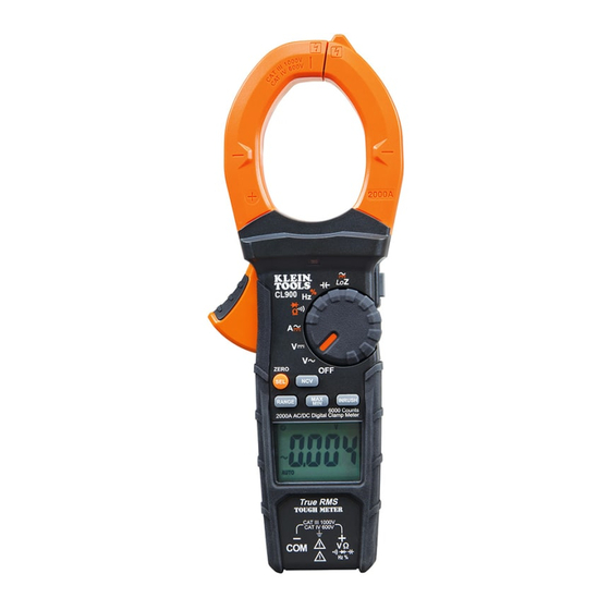
2000A
Digital Clamp Meter
True RMS
Measurement
Technology
• NON-CONTACT
VOLTAGE TESTING
• INRUSH CURRENT
• LOW IMPEDANCE
• DATA HOLD
• RANGE HOLD
• AUDIBLE
CONTINUITY
• DIODE TEST
• CAPACITANCE
• FREQUENCY
1000V
2000A
60M
Ω
2 m
IP40
ESPAÑOL
pg. 17
FRANÇAIS
pg. 33
GlobalTestSupply
www.
CL900
4007177
.com
sales@GlobalTestSupply.com
Advertisement
Table of Contents

Related Manuals for Klein Tools CL900


Summary of Contents for Klein Tools CL900
- Page 1 CL900 ENGLISH INSTRUCTION MANUAL 2000A Digital Clamp Meter True RMS Measurement Technology • NON-CONTACT VOLTAGE TESTING • INRUSH CURRENT • LOW IMPEDANCE • DATA HOLD • RANGE HOLD • AUDIBLE CONTINUITY • DIODE TEST • CAPACITANCE • FREQUENCY 1000V 2000A Ω...
-
Page 2: General Specifications
ENGLISH GENERAL SPECIFICATIONS Klein Tools CL900 is an auto-ranging, true root mean square (TRMS) digital clamp meter that measures AC/DC current via the clamp and measures AC/DC voltage, resistance, continuity, frequency, duty- cycle, capacitance, and tests diodes via test-leads. It features a Low Impedance (LoZ) mode for identifying and eliminating ghost or stray voltages, and has a dedicated mode for capturing Inrush Current. -
Page 3: Electrical Specifications
ELECTRICAL SPECIFICATIONS Function Range Resolution Accuracy (50/60 Hz) 600.0mV 0.1mV ±(1.0% + 8 digits)* 6.000V ±(1.0% + 5 digits) AC Voltage 60.00V 10mV (V AC) ±(1.2% + 5 digits) 600.0V 0.1V 1000V ±(1.5% + 5 digits) 600.0mV 0.1mV ±(0.9% + 8 digits) 6.000V DC Voltage 60.00V... - Page 4 ENGLISH ELECTRICAL SPECIFICATIONS 9.999Hz 0.001Hz 99.99Hz 0.01Hz 999.9Hz 0.1Hz Frequency ±(1.0% + 5 digits) 9.999kHz 99.99kHz 10Hz 500.0kHz 100Hz Sensitivity: >8V RMS, Maximum Input: 600V DC or 600V AC RMS Duty Cycle 0.1% – 99.9% 0.10% ±(1.2% + 2 digits) Pulse width: 0.1ms –...
-
Page 5: Symbols On Lcd
WARNINGS • Always adhere to local and national safety codes. Use personal protective equipment to prevent shock and arc blast injury where hazardous live conductors are exposed. • Usage of this meter in any way other than that specified by the manufacturer can impair safe operation, resulting in severe injury or death. -
Page 6: Feature Details
ENGLISH FEATURE DETAILS 6000 count LCD display Function selector switch Clamp "COM" jack "VΩ" jack Data Hold / Backlight button "RANGE" button "MAX/MIN" button SEL (select) / DC Zero button INRUSH button Clamp trigger (press to open clamp) Arrow markings Non-contact Voltage Testing Button... -
Page 7: Function Buttons
FUNCTION BUTTONS ON/OFF To power ON the meter, rotate the Function Selector switch from the OFF setting to any measurement setting. To power OFF the meter, rotate the Function Selector switch to the OFF setting. By default, the meter will automatically power OFF after aprox. 30 minutes of inactivity. -
Page 8: Inrush Current
ENGLISH FUNCTION BUTTONS MAX/MIN When the "MAX/MIN" button is pressed, the meter keeps track of the Maximum and Minimum values as the meter continues to take samples. 1. When measuring, press "MAX/MIN" button to toggle between the Maximum value (MAX) and Minimum value (MIN). If a new Maximum or Minimum, the display will update with the new value. - Page 9 OPERATING INSTRUCTIONS CONNECTING TEST LEADS Do not test if leads are improperly seated. Results could cause intermittent display readings. To ensure proper connection, firmly press leads into the input jack completely. CORRECT INCORRECT TESTING IN CAT III / CAT IV MEASUREMENT LOCATIONS Ensure the test lead shield is pressed firmly in place.
- Page 10 ENGLISH OPERATING INSTRUCTIONS AC/DC CURRENT (LESS THAN 2000A) AC Current is measured by pressing the clamp trigger to open the clamp and placing it around a current-carrying wire. When measuring, care should be taken to ensure that the clamp is completely closed with trigger fully released, and that the wire passes perpendicularly through...
- Page 11 OPERATING INSTRUCTIONS AC/DC VOLTAGE (LESS THAN 1000V) 1. Insert RED test lead into VΩ jack , and BLACK test lead into COM jack , and rotate function selector switch to the AC voltage V or DC voltage V setting. The AC or DC icon on the LCD indicates which setting is selected.
-
Page 12: Resistance Measurements
ENGLISH OPERATING INSTRUCTIONS CONTINUITY 1. Insert RED test lead into VΩ jack , and BLACK test lead into COM jack , and rotate function selector switch to the Continuity/Resistance/Diode-Test setting. Black lead Red lead NOTE: The meter defaults to Continuity testing in this setting. Ensure that the Continuity Testing icon is visible on the display. -
Page 13: Diode Test
OPERATING INSTRUCTIONS DIODE TEST 1. Insert RED test lead into VΩ jack , and BLACK test lead into COM jack , and rotate function selector switch to the Continuity/Resistance/Diode-Test setting. Black lead Red lead NOTE: The meter defaults to Continuity testing in this mode. Press the SEL/DC ZERO"... -
Page 14: Maintenance
ENGLISH OPERATING INSTRUCTIONS CAPACITANCE 1. Insert RED test lead into VΩ jack , and BLACK test lead into COM jack , and rotate function selector switch to the Capacitance setting. Black lead Red lead 2. Remove power from circuit. 3. Measure capacitance by connecting test leads across the capacitor. The meter will auto-range to display the measurement in the most appropriate range. -
Page 15: Warranty
CLEANING Be sure meter is turned off and wipe with a clean, dry lint-free cloth. Do not use abrasive cleaners or solvents. STORAGE Remove the batteries when meter is not in use for a prolonged period of time. Do not expose to high temperatures or humidity.
Need help?
Do you have a question about the CL900 and is the answer not in the manual?
Questions and answers