Klein Tools CL120 Instruction Manual
400a ac auto-ranging digital clamp meter
Hide thumbs
Also See for CL120:
- User manual ,
- Instruction manual (37 pages) ,
- Instruction manual (13 pages)
Table of Contents
Advertisement
Quick Links
ENGLISH
INSTRUCTION MANUAL
INSTRUCTION MANUAL
400A AC Auto-Ranging
400A AC Auto-Ranging
400A AC Auto-Ranging
Digital Clamp Meter
Digital Clamp Meter
Digital Clamp Meter
• NON-CONTACT
VOLTAGE TESTING
• AUTO-RANGING
• DATA HOLD
• RANGE HOLD
• AUDIBLE
CONTINUITY
600V
400A
20M
Ω
2 m
Vi Visit us at www.TestEquipmentDepot.com
5 Commonwealth Ave
5 Commonwealth Ave
5 Commonwealth Ave
5 Commonwealth Ave
Woburn, MA 01801
Woburn, MA 01801
Woburn, MA 01801
Woburn, MA 01801
Phone 781-665-1400
Phone 781-665-1400
Phone 781-665-1400
Phone 781-665-1400
Toll Free 1-800-517-8431
Toll
Toll
Toll
Free 1-800-517-8431
Free 1-800-517-8431
Free 1-800-517-8431
CL120KIT
CAT III
600V
Advertisement
Table of Contents

Related Manuals for Klein Tools CL120


Summary of Contents for Klein Tools CL120
- Page 1 ENGLISH CL120KIT INSTRUCTION MANUAL INSTRUCTION MANUAL 400A AC Auto-Ranging 400A AC Auto-Ranging 400A AC Auto-Ranging Digital Clamp Meter Digital Clamp Meter Digital Clamp Meter • NON-CONTACT VOLTAGE TESTING • AUTO-RANGING • DATA HOLD • RANGE HOLD • AUDIBLE CONTINUITY 600V 400A Ω...
-
Page 2: General Specifications
ENGLISH GENERAL SPECIFICATIONS Klein Tools CL120 is an automatically ranging digital clamp-meter that measures AC current via the clamp, and AC/DC voltage, resistance and continuity via test-leads. • Operating Altitude: 6562 ft. (2000 m) • Relative Humidity: <95% non-condensing • Operating Temp: 32° to 122°F (0° to 50°C) •... -
Page 3: Electrical Specifications
ELECTRICAL SPECIFICATIONS Function Range Resolution Accuracy 200.0mV 0.1mV ±(2.5% + 10 digits) 2.000V AC Voltage 20.00V 10mV (V AC) ±(2.0% + 5 digits) 200.0V 100mV 600V 200.0mV 0.1mV ±(1.0% + 8 digits) 2.000V DC Voltage 20.00V 10mV (V DC) ±(1.0% + 3 digits) 200.0V 100mV 600V... -
Page 4: Symbols On Lcd
ENGLISH WARNINGS To ensure safe operation and service of the meter, follow these instructions. Failure to observe these warnings can result in severe injury or death. • Before each use verify meter operation by measuring a known voltage or current. •... -
Page 5: Feature Details
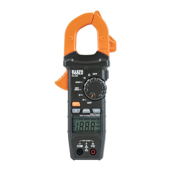
FEATURE DETAILS NOTE: There are no user-serviceable parts inside meter. 2000 count LCD display "MAX" (Maximum) button Function selector switch Data Hold button Clamp Clamp trigger "COM" jack Arrow markings "VΩ" jack NCV Button Backlight button NCV Light "RANGE" button NCV Sensing Antenna Test Equipment Depot - 800.517.8431 - 5 Commonwealth Ave, Woburn, MA 01801 TestEquipmentDepot.com... -
Page 6: Function Buttons
ENGLISH FUNCTION BUTTONS ON/OFF To power ON the meter, rotate the Function Selector switch from the OFF setting to any measurement setting. To power OFF the meter, rotate the Function Selector switch to the OFF setting. The Auto- Power Off icon will be visible in the display. - Page 7 OPERATING INSTRUCTIONS CONNECTING TEST LEADS Do not test if leads are improperly seated. Results could cause intermittent display readings. To ensure proper connection, firmly press leads into the input jack completely. INCORRECT CORRECT TESTING IN CAT III MEASUREMENT LOCATIONS Ensure the test lead shield is pressed firmly in place. Failure to use the CATIII / CATIV shield increases arc-flash risk.
- Page 8 ENGLISH OPERATING INSTRUCTIONS AC CURRENT (LESS THAN 400A) AC Current is measured by pressing the clamp trigger to open the clamp and placing it around a current-carrying wire. When measuring, care should be taken to ensure that the clamp is completely closed with trigger fully released, and that the wire passes perpendicularly through the center of the clamp in line with...
- Page 9 OPERATING INSTRUCTIONS AC/DC VOLTAGE (LESS THAN 600V) 1. Insert RED test lead into VΩ jack , and BLACK test lead into COM jack , and rotate function selector switch to the DC Voltage or AC Voltage setting. Note "DC" or "AC" on the display.
-
Page 10: Resistance Measurements
ENGLISH OPERATING INSTRUCTIONS RESISTANCE MEASUREMENTS 1. Insert RED test lead into VΩ jack , and BLACK test lead into COM jack , and rotate function selector switch to the Resistance setting. The resistance symbol will appear on the display. 2. Remove power from circuit. 3. -
Page 11: Maintenance
MAINTENANCE BATTERY REPLACEMENT When indicator is displayed on LCD, batteries must be replaced. 1. Loosen captive screw and remove battery cover. 2. Replace 3 x AAA batteries (note proper polarity). 3. Replace battery cover and fasten screw securely. To avoid risk of electric shock, disconnect leads from any voltage source before removing battery door. - Page 12 ENGLISH CLEANING Be sure meter is turned off and wipe with a clean, dry lint-free cloth. Do not use abrasive cleaners or solvents. STORAGE Remove the batteries when meter is not in use for a prolonged period of time. Do not expose to high temperatures or humidity.
- Page 13 RT210 GENERAL SPECIFICATIONS Relative Humidity: < 85% non-condensing Operating Temperature: 32° to 140°F (0° to 40°C) Storage Temperature: 14° to 122°F (-10°C to 50°C) Weight: 1.3 oz. (37 g) Nominal Power: 0.3W Certification: Conforms To UL Std 1436 Certified To CSA Std C22.2 # 160 Drop Protection: 6.6 ft.
-
Page 14: Standard Receptacles
ENGLISH WIRING CONFIGURATION TESTING Conditions indicated: wiring correct, open ground, reverse polarity, open hot, open neutral and hot/ground reversed. Conditions NOT indicated: quality of ground, multiple hot wires, combinations of defects, reversal of grounded and grounding conductors. All appliances or equipment on the circuit being tested should be unplugged to help reduce the possibility of erroneous readings. - Page 15 15A without splitting the device or appliances power cord. It has been designed for use with Klein Tools clamp meters, but will also function with many other manufacturers’ clamp meters.
- Page 16 ENGLISH USING THE LINE SPLITTER (FIG. 2) 1. Plug Line Splitter 10x into receptacle. 2. Plug the load (appliance or device) into the line splitter. 3. Measure current by clamping the clamp meter around the Line Splitter 10x. 4. The current measured by the clamp meter is 10x the actual current present in the circuit.
Need help?
Do you have a question about the CL120 and is the answer not in the manual?
Questions and answers