
Related Manuals for Ortur Y-axis


Summary of Contents for Ortur Y-axis
- Page 1 User Manual of Y Axis Rotary Roller Dongguan Ortur Intelligent Technologies Co., Ltd.
- Page 2 (EN)Address: No. 56 Maxin Road, Changping Town, Dongguan 523565, Guangdong Province, China (FR)Adresse: No. 56 Route Maxin, Changping Town, Dongguan 523565, Province de Guangdong, Chine (DE)Adresse: 56 Maxin Road, Stadt Changping, Dongguan 523565, Provinz Guangdong, China (IT)Indirizzo: No. 56 Maxin Road, Città Changping, Dongguan 523565, Provincia del Guangdong, Cina (ES)Dirección: 56 Maxin Road, Ciudad Changping, Dongguan 523565, Provincia de Guangdong, China...
-
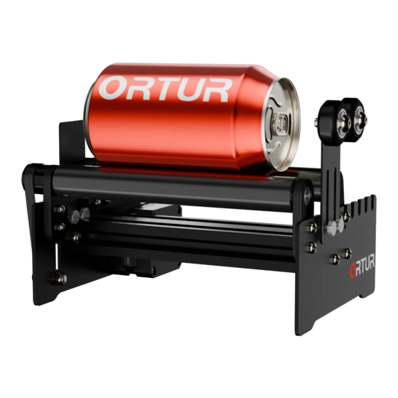
Page 3: Brief Introduction
This Y-axis Rotary Roller is an accessory part of Laser Engraver, cannot be used alone. Attention This Y-axis Rotary Roller could be used with other brands of laser engraver, but it does not guarantee a perfect match. If user modifies the Y-axis Rotary Roller without permission, we would... -
Page 4: Assembly Procedure
Assembly Procedure 1. Assemble the Frame and Motor by 4 x M3*8 screws and 4 x M5*10 screws M5*10 Screw ×4Pcs M3*8 Screw ×4Pcs 2. Assemble the Idle Pulley Bearing ×4Pcs M5 Nut ×2Pcs 5.3mm Spacer ×2Pcs M5 Locknut ×2Pcs M5*20 Screw ×2Pcs... - Page 6 3. Assemble Roller Bearing ×2Pcs Bearing ×2Pcs M5*10 Screw ×4Pcs M5 Nut ×4Pcs Note: The screws here should not be tightened for now, and the installation gap should be reserved.
- Page 7 M5 Nut ×4Pcs M5*10 Screw ×4Pcs...
- Page 8 4. Assemble Timing Belt Pulleys. 25 Teeth Timing Belt Pulley ×2Pcs 16 Teeth Timing Belt Pulley ×1Pc 5. Last Step.
- Page 9 Insert the timing belt, adjust the position of each Timing Belt Pulley, and use the hex wrench to tighten the internal fixing screw.
- Page 10 The distance between the two rollers can be adjusted according to actual needs...
-
Page 11: Setting Procedure
Setting Procedure Turn off the Automatic Home function. (Please skip this step if your laser engraver does not have this function.) 1.Turn on the laser engraver, open the LaserGRBL software on computer, and connect the laser engraver. 2.Unlock the laser engraver. 2.Unlock the laser engraver. - Page 12 3.Open Grbl Configuration.
- Page 13 4. Change the value here to 0, to turn off the Automatic Return to Origin function. 5.Write data to the main 6.Close the window. board.
- Page 14 1.1. Place the subject as shown in the figure below, and connect with the laser engraver by a 500MM extension cable. Heighten the laser engraver according to Unplug the Y Motor Cable, and the height of the object. connect this Y Motor Cable and the Y-axis Rotary Roller by the extension cable.
- Page 15 1.2. Adjust the position and laser focus, then start engraving. WARNING: Must wear eye protection (Laser goggles) before operating laser !!! The laser spot should be aligned with the apex of the cylinder object.
- Page 16 2. The installation method for marching with frame laser engraver: 2.1. Place the subject as shown in the figure below, and connect with the laser engraver Heighten the laser engraver according to the height of the object.
- Page 17 Unplug the Y Motor Cable, and connect this Y Motor Cable and the Y-axis Rotary Roller by the extension cable. 2.2. Adjust the position and laser focus, then start engraving. PS. DO wear eye protection (Laser goggles) before operating laser !!! The laser spot should be aligned with the apex of the cylinder object.
Need help?
Do you have a question about the Y-axis and is the answer not in the manual?
Questions and answers