Table of Contents
Advertisement
Quick Links
KA01371D/06/EN/02.19
71452945
2019-09-10
Products
Brief Operating Instructions
Teqwave F/I
Device with acoustic surface wave technology
These Instructions are Brief Operating Instructions; they are
not a substitute for the Operating Instructions pertaining to
the device.
Detailed information about the device can be found in the
Operating Instructions and the other documentation:
• On the CD-ROM supplied (not included in the delivery for all
device versions).
• Available for all device versions via:
• Internet:
www.endress.com/deviceviewer
• Smart phone/tablet: Endress+Hauser Operations App
Solutions
Services
Advertisement
Table of Contents

Related Manuals for Endress+Hauser Teqwave F/I


Summary of Contents for Endress+Hauser Teqwave F/I
- Page 1 Detailed information about the device can be found in the Operating Instructions and the other documentation: • On the CD-ROM supplied (not included in the delivery for all device versions). • Available for all device versions via: • Internet: www.endress.com/deviceviewer • Smart phone/tablet: Endress+Hauser Operations App...
- Page 2 Teqwave F/I Order code: XXXXX-XXXXXX Ser. no.: XXXXXXXXXXXX Ext. ord. cd.: XXX.XXXX.XX Serial number www.endress.com/deviceviewer Endress+Hauser Operations App A0023555 Endress+Hauser...
-
Page 3: Table Of Contents
Teqwave F/I Table of contents Table of contents About this document ............. . 4 Symbols used . -
Page 4: About This Document
About this document Teqwave F/I About this document Symbols used 1.1.1 Safety symbols DANGER This symbol alerts you to a dangerous situation. Failure to avoid this situation will result in serious or fatal injury. WARNING This symbol alerts you to a dangerous situation. Failure to avoid this situation can result in serious or fatal injury. - Page 5 Teqwave F/I About this document 1.1.3 Electrical symbols Symbol Meaning Symbol Meaning Direct current Alternating current Direct current and alternating current Ground connection A grounded terminal which, as far as the operator is concerned, is grounded via a grounding system.
-
Page 6: Basic Safety Instructions
Basic safety instructions Teqwave F/I 1.1.5 Tool symbols Symbol Meaning Symbol Meaning Torx screwdriver Flat blade screwdriver Cross-head screwdriver Allen key Open-ended wrench 1.1.6 Symbols in graphics Symbol Meaning Symbol Meaning 1, 2, 3,... Item numbers … Series of steps A, B, C, ... -
Page 7: Workplace Safety
Verification for borderline cases: ‣ For special fluids and fluids for cleaning, Endress+Hauser is glad to provide assistance in verifying the corrosion resistance of fluid-wetted materials, but does not accept any warranty or liability as minute changes in the temperature, concentration or level of contamination in the process can alter the corrosion resistance properties. -
Page 8: Operational Safety
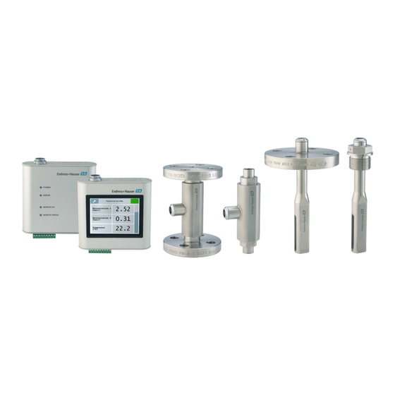
It meets general safety standards and legal requirements. It also complies with the EU directives listed in the device-specific EU Declaration of Conformity. Endress+Hauser confirms this by affixing the CE mark to the device. IT security Our warranty is valid only if the device is installed and used as described in the Operating Instructions. - Page 9 Teqwave F/I Product description 3.1.1 Sensor A0035451 1 Sensor versions "Teqwave F" sensor "Teqwave I" sensor Push-pull connection for connecting to the transmitter 3.1.2 Transmitter A0035452 2 Transmitter versions Transmitter with LED status indication Transmitter with a touchscreen...
-
Page 10: Installation
The concentration app is a file with lmf format. A list of the available concentration apps is provided in the Applicator . If you require a concentration app that is not already listed in the Applicator, Endress+Hauser requires a sample of the fluid to create the concentration app. Every transmitter can use a maximum of 25 concentration apps. - Page 11 Teqwave F/I Installation Orientation Teqwave I A0035457 4 Orientation of Teqwave I Mount Teqwave I so that the active sensor area can be fully immersed in the measured liquid. If installing the sensor in a pipe, make sure the sensor is aligned correctly to avoid irregular flow to the sensor.
-
Page 12: Mounting The Measuring Device
Installation Teqwave F/I ≥ 10 × DN ≥ 5 × DN A0035458 5 Inlet and outlet runs Mounting the measuring device 4.2.1 Installing the sensor WARNING Danger due to improper process sealing ‣ Use seals whose internal diameters are larger than or the same size as the process connection and pipe. -
Page 13: Post-Mounting Check
Teqwave F/I Installation A0035459 6 Mounting the transmitter DIN rail holder DIN rail according to DIN EN 60715 TH 35 Mount the transmitter on the DIN rail using the DIN rail holder. Post-mounting check Perform the following checks once you have installed the measuring device:... -
Page 14: Electrical Connection
Electrical connection Teqwave F/I Electrical connection The measuring device does not have an internal circuit breaker. For this reason, assign the measuring device a switch or power-circuit breaker that allows the power supply line to be easily disconnected from the mains. -
Page 15: Connecting The Measuring Device
Teqwave F/I Electrical connection Terminal Assignment Analog output 0 to 10 V; 4 to 20 mA output Digital input selection Signal ground alarm Relay output max. 50 V, 1 A 5.1.3 Requirements for supply unit Supply voltage DC 24 V (nominal voltage: DC 18 to 35 V) Power unit The power unit must be tested to ensure it meets safety requirements (e.g. - Page 16 Electrical connection Teqwave F/I 7 Connecting the connecting cable Insert the push-pull connector of the connecting cable into the socket at the position indicated until they engage with a click. Red dots on the connectors indicate the position. 5.2.2 Connecting the supply voltage cables The measuring device does not have an internal circuit breaker.
-
Page 17: Special Connecting Instructions
Teqwave F/I Electrical connection Special connecting instructions 5.3.1 Connecting examples Current output 4 to 20 mA 4...20 mA A0028758 8 Connection example for current output, active, 4 to 20 Automation system with current input (e.g. PLC) Analog display unit: maximum load 500 Ω... - Page 18 Electrical connection Teqwave F/I Relay output A0035461 10 Connection example for relay output, passive Automation system with switch input (e.g. PLC) Power supply: max. 50 V AC/DC Transmitter Digital input (elective inputs) The digital input can create up to four measured variables on the analog output.
-
Page 19: Post-Connection Check
Teqwave F/I Electrical connection A0035462 11 Connection example for the digital input Automation system with switch input (e.g. PLC) Power supply Transmitter If the transmitter is connected as illustrated in the example, the outputs are no longer galvanically isolated. -
Page 20: Operating Options
Operating options Teqwave F/I Operating options Overview of the operating options The measuring device can be operated in the following ways: • Operation via the local display (transmitter with touch screen) • Operation via the "Teqwave Viewer" operating tool supplied... - Page 21 Teqwave F/I Operating options seven measured values can be displayed. If there are several measured values, users must scroll down using the scroll bar on the right to be able see all the measured variables. Functions of the display and operating elements...
- Page 22 Operating options Teqwave F/I Editing elements Numeric editor Text editor A0035468 A0035469 Display area for the entered values Display area for the entered values Input mask Input mask Input mask The following input symbols are available in the input mask of the numeric and text editor:...
-
Page 23: Access To The Measuring Device Via The Operating Tool
Teqwave F/I Commissioning 6.2.2 LED status indication (transmitter with LED status indication) For a description, see "Diagnostics information for transmitter with LED status indication" → 34. Access to the measuring device via the operating tool For detailed information on access to the measuring device, see the Operating Instructions for the device. -
Page 24: Configuring The Measuring Device
Commissioning Teqwave F/I Navigation using transmitter with touch screen Settings menu → "Language settings" Once the user has selected the language, the operating tool communicates the language setting to the transmitter. Parameter Procedure Selection/input Factory setting Language settings Tap to select the language. - Page 25 Teqwave F/I Commissioning 7.4.3 Configuring the measuring unit All the measured values are configured via the Measuring unit menu (transmitter with touch screen) or via the View settings menu (Viewer). • The measured value is automatically converted if the unit is changed.
- Page 26 Commissioning Teqwave F/I Menu "Teqwave Transmitter" → "Application parameters" → "Test signal"' • The operating tool communicates the settings to the transmitter as soon as the Apply button is clicked. • For detailed information on the parameters, see the Operating Instructions for the device.
- Page 27 Teqwave F/I Commissioning Settings menu → "Application parameters" → "Relay output" → "Settings" → Select measured value → "Switch point Max"/"Switch point Min" or "Switch point" Settings menu → "Application parameters" → "Relay output" → "Settings" → Select measured value → "Hysteresis"...
- Page 28 Commissioning Teqwave F/I Menu "Teqwave Transmitter" → "Averaging" → Select "Temperature" → "Kalman filter" • The operating tool communicates the settings to the transmitter as soon as the Apply button is clicked. • For detailed information on the parameters, see the Operating Instructions for the device.
-
Page 29: Advanced Settings
Teqwave F/I Commissioning Settings menu → "Application parameters" → "Diagnosis" → "Process disturbance" → "Switch point" Navigation using the Viewer Menu "Teqwave Transmitter" → "' V iew filter" → "Filter options" and "Filter actions"' Menu "Teqwave Transmitter" → "' V iew filter" → "Change in" → Select measured variable Menu "Teqwave Transmitter"... - Page 30 7.6.2 Activation Endress+Hauser provides users with a license key to activate the functions. The license key must be entered to enable the functions of the application package. The key is entered in the Viewer via the "Teqwave Transmitter" → "License key" menu.
-
Page 31: Diagnostics And Troubleshooting
Teqwave F/I Diagnostics and troubleshooting Navigation using the Viewer Menu "Teqwave Transmitter" → "Storage interval" • The operating tool communicates the settings to the transmitter as soon as the Apply button is clicked. • For detailed information on the parameters, see the Operating Instructions for the device. - Page 32 Diagnostics and troubleshooting Teqwave F/I 8.1.3 For output signals Problem Possible causes Remedial action Signal output outside the valid range. Incorrect configuration. Check the configuration and correct if necessary. Stay within the specifications for the outputs indicated in the "Technical data".
- Page 33 Teqwave F/I Diagnostics and troubleshooting Problem Possible causes Remedial action Sensor is fouled. Make sure the sensor is free from dirt and deposit build-up. Sensor is defective. Check the sensor with the "Check sensor" function. Contact Endress+Hauser Service if limit value is exceeded.
-
Page 34: Diagnostics Information For Transmitter With Led Status Indication
Diagnostics and troubleshooting Teqwave F/I Diagnostics information for transmitter with LED status indica- tion Four light emitting diodes (LEDs) on the transmitter provide information on the condition of the device. Transmitter with LED status indication Signal Meaning Power Lit green Supply voltage connected, initialization completed. - Page 35 Teqwave F/I Diagnostics and troubleshooting Signal color Diagnostic message Description Measures "Process disturbance The measured dispersion is Remove air bubbles and/or detected, dispersion greater than the configured particles. > [limit value]" switch point. Take recommended mounting position into consideration → 10.
-
Page 36: Diagnostic Information Via The Modbus Protocol
Diagnostics and troubleshooting Teqwave F/I Signal color Diagnostic message Description Measures "Temperature chip Sensor is defective. Contact Endress+Hauser Service. faulty" "Sensor memory Sensor is defective. Contact Endress+Hauser Service. faulty" "System is starting" Measuring device is initializing. Contact Endress+Hauser Service. "Process disturbance"... -
Page 37: Diagnostics Information Via Dispersion Indicator
Teqwave F/I Diagnostics and troubleshooting Hexadecimal Diagnostic Description Measures message 0x00000100 Process disturbance The measured Remove air bubbles and/or detected dispersion is greater particles. than the configured Take recommended switch point. mounting position into consideration → 10 0x00000200 Process disturbance... - Page 40 www.addresses.endress.com...
Need help?
Do you have a question about the Teqwave F/I and is the answer not in the manual?
Questions and answers