
Related Manuals for Endress+Hauser Flowphant T ODTT31


Summary of Contents for Endress+Hauser Flowphant T ODTT31
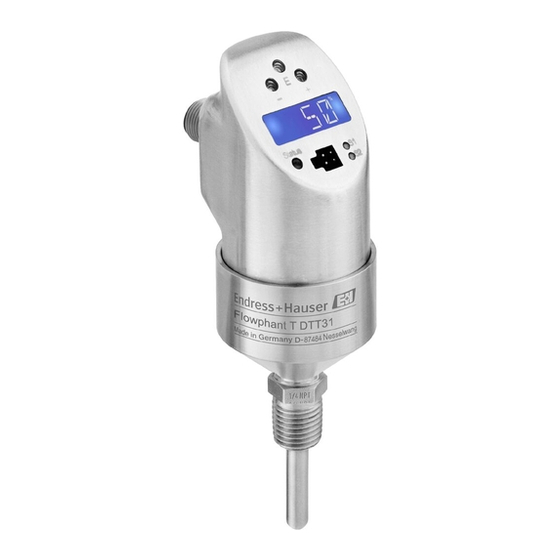
- Page 1 BA00235O/09/EN/17.20 71509928 2020-12-15 Valid as of version 01.00 (device version) Operating Instructions Flow switch ODTT31, ODTT35 For safe monitoring of mass flow rates and temperature in industrial processes...
-
Page 3: Table Of Contents
Flow switch ODTT31, ODTT35 Table of contents Table of contents About this document ... 4 10.2 Communication-specific accessories . . . 36 Document function ....4 Technical data . -
Page 4: About This Document
About this document Flow switch ODTT31, ODTT35 About this document Document function These Operating Instructions contain all the information that is required in various phases of the life cycle of the device: from product identification, incoming acceptance and storage, to mounting, connection, operation and commissioning through to troubleshooting, maintenance and disposal. - Page 5 Flow switch ODTT31, ODTT35 About this document 1.2.3 Symbols for certain types of information Symbol Meaning Permitted Procedures, processes or actions that are permitted. Preferred Procedures, processes or actions that are preferred. Forbidden Procedures, processes or actions that are forbidden. Indicates additional information.
-
Page 6: Basic Safety Instructions
Basic safety instructions Flow switch ODTT31, ODTT35 Basic safety instructions Requirements for the personnel The personnel for installation, commissioning, diagnostics and maintenance must fulfill the following requirements: ‣ Trained, qualified specialists must have a relevant qualification for this specific function and task. -
Page 7: Product Safety
Flow switch ODTT31, ODTT35 Incoming acceptance and product identification Risk of injury! ‣ Operate the device in proper technical condition and fail-safe condition only. ‣ The operator is responsible for the interference-free operation of the device. Modifications to the device Unauthorized modifications to the device are not permitted and can lead to unforeseeable dangers: ‣... -
Page 8: Product Identification
Compare and check the data on the nameplate of the device against the requirements of the measuring point. Name and address of manufacturer Name of manufacturer: Endress+Hauser Wetzer GmbH + Co. KG Address of manufacturer: Obere Wank 1, D-87484 Nesselwang or www.endress.com... -
Page 9: Certificates And Approvals
Flow switch ODTT31, ODTT35 Mounting Certificates and approvals 3.4.1 CE mark The product meets the requirements of the harmonized European standards. As such, it complies with the legal specifications of the EC directives. The manufacturer confirms successful testing of the product by affixing to it the CE-mark. 3.4.2 Hygiene standard •... - Page 10 Mounting Flow switch ODTT31, ODTT35 NOTICE Damage to the device. ‣ Do not turn the device into the process connection thread at the housing→ 10. ‣ Always install the device at the wrench flats. ‣ Use a suitable open-ended wrench → 10. ‣...
- Page 11 Flow switch ODTT31, ODTT35 Mounting • The sensor tip must be completely surrounded by the medium • Position the sensor tip in the area of maximum flow velocity (pipe center) • Minimum sensor immersion length ≥ 10 mm (0.4 in). A0006976 ...
- Page 12 Mounting Flow switch ODTT31, ODTT35 NOTICE If the device is installed incorrectly this can result in incorrect measurements! ‣ Do not install in down pipes open towards the end. ‣ The sensor tip should never touch the pipe wall. A0006978 ...
- Page 13 Flow switch ODTT31, ODTT35 Mounting 4.1.4 Installation instructions when installing in hygienic processes R0.4 R0.4 A0044659 5 Detailed installation instructions for hygiene-compliant installation Milk pipe connection according to DIN 11851 (PL, PG, PH connection), only in conjunction with EHEDG-certified and self-centering sealing ring 1.1 Sensor with milk pipe connection 1.2 Groove slip-on nut 1.3 Counterpart connection...
- Page 14 Mounting Flow switch ODTT31, ODTT35 Avoid crevices, folds or gaps. Ensure the surface is honed and polished, Ra ≤ 0.76 µm (30 µin). Pay attention to the following when installing the thermometer to ensure that the cleanability is not affected: The installed sensor is suitable for CIP (cleaning in place).
-
Page 15: Electrical Connection
Flow switch ODTT31, ODTT35 Electrical connection 3 × DN 5 × DN 3 × DN 5 × DN 3 × DN 5 × DN 3 × DN 15 × DN 3 × DN 10 × DN 5 × DN 3 × DN A0023225 ... - Page 16 Electrical connection Flow switch ODTT31, ODTT35 A2’ L– L– 4...20 mA L– A0006818 7 Flow switch with M12x1 connector Item no. Output setting 1x PNP switch output 2x PNP switch output R1 and Rx (R2) A2’ 2x PNP switch output R1 and Rx (diagnostics/NC contact with "DESINA" setting) 1x PNP switch output and 1x analog output (4 to 20 mA) WARNING...
-
Page 17: Operating Options
Flow switch ODTT31, ODTT35 Operating options 5.1.2 DC voltage version with valve connector L– A0035798 8 Flow switch with M16x1.5 valve connector or NPT ½" Item no. Output setting 1x PNP switch output Operating options Overview of operating options The device is operated via three keys. - Page 18 Operating options Flow switch ODTT31, ODTT35 A0044663 9 Position of the operating elements and possibilities for display Operating keys Digital display: illuminated white (= ok); red (= alarm/error) Yellow LED for switching states: LED on = switch closed; LED off = switch open Communication jack for PC configuration LED for status display: green = OK;...
-
Page 19: Structure And Function Of The Operating
Flow switch ODTT31, ODTT35 Operating options Structure and function of the operating menu 6.2.1 Navigation in the operating menu BASE > 3 s SAVE > 3 s A0035802 10 Navigation in the operating menu Function group selection Function selection To enter the operating menu, press the E key for longer than 3 s. - Page 20 Operating options Flow switch ODTT31, ODTT35 6.2.2 Navigating the Calibration (CAL) function group Variable limits for HIF (Learn High Flow) or LOWF (Learn Low Flow) can be set with the ' L earn Function' . • HIF setting (Learn High Flow): Enter any flow rate from 70 to 100 % of the maximum value in the process.
- Page 21 Flow switch ODTT31, ODTT35 Operating options Or: The message "W432" appears on the display after 60 s. A sufficiently stable flow could not be detected during the learning process. The system takes an average of the 10 values last measured during the learning process. Return to the CAL function group (Home position) with the E key.
- Page 22 Operating options Flow switch ODTT31, ODTT35 NOK: The switch point determined is under 5 % of the measuring range and cannot be accepted because the switch point must be at least 5 % greater than the switchback point (RSP). The device is still operative if message "W432" or "NOK" is displayed. There can be large deviations at the switch point, however.
- Page 23 Flow switch ODTT31, ODTT35 Operating options 6.2.4 Structure of the operating menu for 2 switch outputs BASE DISP PVRO TMPR OFFR UNIT °C °F DESI WAIT WAIT LOWF FUNC HYNC HYNO WAIT TRSP OUT2 MODE FLOW TEMP (optional) UNIT °C °F FNC2 HYNC...
- Page 24 Operating options Flow switch ODTT31, ODTT35 Function groups Functions Settings 6.2.5 Structure of the operating menu for 1 x analog output (4 to 20 mA) and 1 x switch output BASE DISP PVRO TMPR OFFR UNIT °C °F WAIT LOWF WAIT 4-20 MODE...
- Page 25 Flow switch ODTT31, ODTT35 Operating options 6.2.6 Basic settings Function group Function Settings Description BASE DISP Display Displays the current measured value Basic settings PVRO Displays the current measured value rotated by 180 ° Display of current medium temperature TMPR Displays the current medium temperature rotated by 180 °...
- Page 26 Operating options Flow switch ODTT31, ODTT35 6.2.8 Settings for output - 2 x switch output Functions of the switch point • Hysteresis function: The hysteresis function enables two-point control via a hysteresis. Depending on the mass flow, the hysteresis can be set via the switch point SP and switchback point RSP.
- Page 27 Flow switch ODTT31, ODTT35 Operating options Function group Function Settings Description Switch point RUN, WAIT: Take the current flow rate as the SP2L "Learn" WAIT switch point SP or SP2.→ 12, 21 Switchback point Enter value 0 to 95 % in increments of 1 %. RSP2 value Factory setting: 40 %...
- Page 28 Operating options Flow switch ODTT31, ODTT35 Function group Function Settings Description Factory setting: °C FUNC Switching HYNC HYNC: hysteresis/NC contact characteristics HYNO HYNO: hysteresis/NO contact → 26 Factory setting: HYNO Value switch Enter value 5 to 100% in increments of 1 %. point Factory setting: 50% Enter value –15 to +85 °C (–5 to +185 °F) in...
-
Page 29: Access To The Operating Menu Via The Operating Tool
Flow switch ODTT31, ODTT35 Operating options Function group Function Settings Description REV'C Static revision Configuration counter, incremented each time counter the configuration is changed. STAT Device status LST'D Last error Displays the last error to occur. Switch output Simulation for 2 No simulation version SIM2... -
Page 30: Diagnostics And Troubleshooting
Diagnostics and troubleshooting Flow switch ODTT31, ODTT35 6.3.1 Additional operating options In addition to the operating options listed in the previous "Local operation" section, further information about the device is available via the configuration software: Function group Function (display) Description SERV (service) Switching operations 1 Number of changes in the switching state for switch... - Page 31 Flow switch ODTT31, ODTT35 Diagnostics and troubleshooting Code Explanation Remedy E011 Device configuration is incorrect Perform device reset → 28 E012 Measurement error or medium temperature outside the Check the medium temperature; return the measurable range device to the manufacturer if necessary E013 Sensor heating defective Return device to manufacturer E019 Power supply out of specification...
-
Page 32: Firmware History
Maintenance Flow switch ODTT31, ODTT35 Firmware history 7.2.1 Release The release number on the nameplate and in the Operating Instructions indicates the device release: XX.YY.ZZ (example 01.02.01). • Change to main version • No longer compatible • The device and Operating Instructions change •... -
Page 33: Cleaning
Flow switch ODTT31, ODTT35 Repair Cleaning The device must be cleaned whenever necessary. Cleaning can also be done when the device is installed (e.g. CIP Cleaning in Place / SIP Sterilization in Place). When cleaning the device, care must be taken to ensure that it is not damaged. NOTICE Avoid damage to the device and the system ‣... -
Page 34: Accessories
Accessories Flow switch ODTT31, ODTT35 Accessories 10.1 Device-specific accessories 10.1.1 Welding boss with sealing taper • Collar welding boss movable with sealing taper, washer 6 (0.24) and pressure screw G½" G½” • Material of parts in contact with the process: 316L, PEEK, AF24 •... - Page 35 Flow switch ODTT31, ODTT35 Accessories 10.1.3 Compression fitting • Movable clamping ring, various process connections 6 (0.24) • Material of compression fitting and parts in contact with the process: 316L • Order number: TA50-..(depending on the process AF14 connection) AF27 G½”...
-
Page 36: Communication-Specific Accessories
Accessories Flow switch ODTT31, ODTT35 Version F in mm (in) L ~ in mm (in) C in B in mm Clampin Max. Max. process (in) g ring process pressure (in) material temperatur R½" SW/AF 22 52 (2.05) 20 (0.8) PTFE 200 °C 5 bar at 20 °C (392 °F) -
Page 37: Technical Data
Flow switch ODTT31, ODTT35 Technical data • PVC cable (terminated), 4 x 0.34 mm with M12x1 coupling, elbowed, screw plug, length 5 m (16.4 ft) • Degree of protection: IP67 • Order number: 51005148 1 (BN) Core colors: 2 (WH) •... -
Page 38: Output
Technical data Flow switch ODTT31, ODTT35 11.1.2 Measuring range Flow 0.03 to 3 m/s (0.1 to 9.84 ft/s), as relative value between 0 to 100%; maximum display resolution: 1% Temperature –20 to +85 °C (–4 to +185 °F); display resolution: 1 °C (1 °F) 11.2 Output 11.2.1... -
Page 39: Environment
Flow switch ODTT31, ODTT35 Technical data Behavior in the event of undervoltage If the supply voltage falls below the minimum value, the device switches off in a defined manner (status as if not supplied with power = switch open) The device may be powered only by a power supply unit that operates using a limited energy circuit in accordance with UL/EN/IEC 61010-1, Section 9.4 and the requirements in Table 18. -
Page 40: Process
Technical data Flow switch ODTT31, ODTT35 11.5 Process 11.5.1 Process temperature range –20 to +85 °C (–4 to +185 °F) The sensor can be exposed to process temperatures up to 130 °C (266 °F) without being damaged. The monitoring system switches off automatically at T ≥ 85 °C (185 °F) and starts again at T ≤... -
Page 41: Mechanical Construction
Flow switch ODTT31, ODTT35 Technical data 11.6 Mechanical construction 11.6.1 Design, dimensions M12x1 M16x1.5 / NPT ½” 38.7 (1.52) 38.7 (1.52) 42.3 (1.66) 24 (0.95) 24 (0.95) 38.5 (1.52) 36 (1.42) 6 (0.24) 6 (0.24) 6 (0.24) A0005279 All dimensions in mm (in) L = insertion length M12x1 connector as per IEC 60947-5-2 Valve connector M16x1.5 or NPT ½"... - Page 42 Technical data Flow switch ODTT31, ODTT35 11.6.2 ODTT31 design, dimensions of process connections L1 = L2 A0007101 21 Process connection versions Insertion length Item Version Thread length L Screw-in length L Without process connection. Suitable welding bosses and compression fittings. → 34 Threaded process connection: ANSI NPT ¼"...
- Page 43 Flow switch ODTT31, ODTT35 Technical data 11.6.3 ODTT35 design, dimensions of process connections 56.5 (2.22) 43.5 (1.71) 64 (2.52) 50.5 (1.99) 61.5 (2.42) 68 (2.68) 50 (1.97) 82 (3.23) G½” 66 (2.6) 84 (3.31) 100 (3.94) 51 (2.01) 39 (1.54) (1.06) 68 (2.68) 56 (2.21)
-
Page 44: Certificates And Approvals
Technical data Flow switch ODTT31, ODTT35 Item no. Process connection versions ODTT35 Hygiene standard DIN 11851, DN25, PN40 (including coupling nut), 316L 3-A marked and EHEDG certified (only in DIN 11851, DN40, PN40 (including coupling nut), conjunction with self-centering seal 316L according to EHEDG position paper) DIN 11851, DN50, PN40 (including coupling nut),... - Page 45 Flow switch ODTT31, ODTT35 Technical data 11.7.2 Other standards and guidelines • IEC 60529: Degrees of protection provided by enclosures (IP code) • IEC/EN 61010-1: Protection Measures for Electrical Equipment for Measurement, Control, Regulation and Laboratory Procedures • IEC/EN 61326 series: Electromagnetic compatibility (EMC requirements) •...
- Page 48 *71509928* 71509928...
Need help?
Do you have a question about the Flowphant T ODTT31 and is the answer not in the manual?
Questions and answers