Table of Contents
Advertisement
Quick Links
Advertisement
Table of Contents

Related Manuals for Dell CMC-PD01


Summary of Contents for Dell CMC-PD01
- Page 1 CMC-PD01 PROFIBUS DP Slave Communication Card Operation Manual CMC-0205820-01...
-
Page 3: Table Of Contents
Communication Parameters for VFD-C2000 Connected to PROFIBUS DP......6 Transmission Distance and Baud Rate ................... 6 Applicable Data Form for CMC-PD01 and Introduction to PKW, PZD........6 Data Formats and Examples ....................7 Reading/Writing AC Motor Drive Parameters by PZD ............11 GSD File............................ -
Page 4: Introduction To Cmc-Pd01
Introduction to CMC-PD01 Product Introduction 1. Thank you for choosing Delta CMC-PD01 communication card. To ensure correct installation and operation of the product, please read this operation manual carefully before using it. 2. This operation manual only provides introductory information on CMC-PD01. Detailed information about PROFIBUS DP protocol is not included in this manual. -
Page 5: Specifications
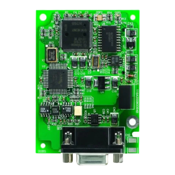
PROFIBUS DP Slave Communication Card CMC-PD01 NET indicator POWER indicator Positioning hole AC motor drive PROFIBUS DP connection Screw fixing hole connection port port Fool-proof groove Specifications PROFIBUS DP Port Interface DB9 connector Transmission method High-speed RS-485 Transmission cable Shielded twisted pair cable... -
Page 6: Installation
PROFIBUS DP Slave Communication Card CMC-PD01 Installation Connecting CMC-PD01 to VFD-C2000 Switch off the power of VFD-C2000. Open the front cover of VFD-C2000. Place the insulation spacer into the positioning pin and aim the two holes on the PCB at the positioning pin. -
Page 7: Definition Of Profibus Dp Port
Sending/receiving data N(A) Connecting to PROFIBUS DP Connector Insert the connector to the connection port on CMC-PD01 and screw up the screws on the connector to ensure tight connection between CMC-PD01 and the PROFIBUS DP connector. See Figure 3.4-1. Figure 3.4-1... -
Page 8: Communication
“Parameter Process data Object” (PPO). Apart from PPO, the cyclical data can be configured as EXT CONF1 or EXT CONF2. Based on different demands, the two extended configurations are able to achieve 4 process data words. See Table 4.3-1 for the data forms CMC-PD01 supports. DVP-PLC Operation Manual... -
Page 9: Data Formats And Examples
PROFIBUS DP Slave Communication Card CMC-PD01 4.3.2 Introduction to PKW, PZD After VFD-C2000 is connected to PROFIBUS DP network through CMC-PD01, there will be two ways to poll AC motor drive parameters, PKW polling and PZD polling. PKW is composed of 4 words, and each word represents particular definition. - Page 10 PROFIBUS DP Slave Communication Card CMC-PD01 4.4.1 PKE (Word 1) PNU (PKE bit0 ~ bit10): Basic parameter number Basic parameter number (PNU) = Address of AC motor drive to be polled – n*2,000 (n = PNU page number). Range of PNU: 1 ~ 1,999 (decimal). PNU page number = 0, when the parameter address of AC motor drive <...
- Page 11 PROFIBUS DP Slave Communication Card CMC-PD01 Sub-index of parameter (IND) bit12 ~ bit15 bit0 ~ bit11 (page number) (Reserved, Default = 0) bit15 bit14 bit13 bit12 bit11 bit10 bit9 bit8 bit7 bit6 bit5 bit4 bit3 bit2 bit1 bit0 Table 1.4-5...
- Page 12 PROFIBUS DP Slave Communication Card CMC-PD01 Master requesting data: Parameters in PKW Parameters in PKW (hex) Word 1 (PKE) 11C3 Word 2 (IND) 2000 Word 3 (PWE1) 0000 Word 4 (PWE2) 0000 Slave responding data: Parameters in PKW Parameters in PKW (hex)
-
Page 13: Reading/Writing Ac Motor Drive Parameters By Pzd
Indication How to correct Power supply in normal Green light on status Check if the connection between CMC-PD01 and No power supply AC motor drive is normsl. NET LED The NET LED displays the connection status of the communication. LED status... -
Page 14: Panel Display On Vfd-C2000 And Trouble-Shooting
VFD-C2000 on the PROFIBUS DP network. When the value of 09-70 is changed, VFD-C2000 has to be re-powered to make the new value valid. 3. Check if VFD-C2000 and CMC-PD01 is firmly connected, and if the wiring of the entire network is correct. - Page 15 PROFIBUS DP Slave Communication Card CMC-PD01 Configuring VFD-C2000 in PROFIBUS network (the software configuration): Create a new project by software wizard. 1. Open SIMATIC Manager. See Figure 7-2. Figure 7-2 2. Select “File” => “New Project Wizard”. See Figure 7-3.
- Page 16 PROFIBUS DP Slave Communication Card CMC-PD01 Figure 7-4 4. Select “CPU315-2 DP” for CPU as we are using the S7-300 model. Click “Next”. See Figure 7-5. Figure 7-5 DVP-PLC Operation Manual...
- Page 17 PROFIBUS DP Slave Communication Card CMC-PD01 5. Select the block and language we need and click “Next”. See Figure 7-6. Figure 7-6 6. Enter the project name and click “Finish”. See Figure 7-7. Figure 7-7 DVP-PLC Operation Manual...
- Page 18 PROFIBUS DP Slave Communication Card CMC-PD01 7. A new window will appear after the project is created. See Figure 7-8. Figure 7-8 Add PROFIBUS DP bus 1. Select “SIMATIC 300 Station” in the project created. See Figure 7-9. Double click “Hardware”, and a new window (HW-Config) will appear.
- Page 19 PROFIBUS DP Slave Communication Card CMC-PD01 2. In the “HW Config” window, double click “DP” in the left-hand side column, and a dialog box will appear. See Figure 7-10. Figure 7-10 3. Click “Properties” in the dialog box, leading to another dialog box. See Figure 7-11.
- Page 20 PROFIBUS DP Slave Communication Card CMC-PD01 4. Select “Address” in the dialog box to be the address of the master. Then click “New” to go to the next dialog box. See Figure 7-12. Figure 7-12 5. Select communication speed and bus type, then click “OK”. See Figure 7-13.
Need help?
Do you have a question about the CMC-PD01 and is the answer not in the manual?
Questions and answers