Table of Contents
Advertisement
Quick Links
USER'S GUIDE UG145
ACT41000EVK1-104 User's Guide
Description
This document describes the characteristics and operation of the Qorvo ACT41000EVK1-104 evaluation kit (EVK). It provides setup
and operation instructions, schematic, layout, BOM, and test data. This EVK demonstrates the ACT41000-104T power management IC.
Other ACT41000QIxxx options can be evaluated on this EVK by replacing the IC and any other necessary components.
Features
The EVK can be used as a standalone board if desired. However, to access the internal registers and to take full advantage of the IC's
capability, the user must connect the EVK to a PC with Qorvo's USB-TO-I2C interface dongle and use the GUI software. The EVK
provides full access to each converter's input and output voltage, as well as all the digital control signals. This gives the user the
flexibility to configure the EVK to match their real-world system
EVK Contents
The ACT41000EVK1-104 evaluation kit comes with the following items:
•
EVK assembly
•
USB-TO-I2C dongle
•
Dongle
•
Custom 4-pin connector that connects the USB-TO-I2C dongle to the EVK assembly
December 2022 Rev 4.0 | Subject to change without notice
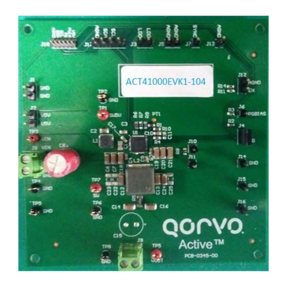
Figure 1. EVK Picture
1 of 20
www.qorvo.com
Advertisement
Table of Contents

Subscribe to Our Youtube Channel
Related Manuals for Qorvo ACT41000EVK1-104


Summary of Contents for Qorvo ACT41000EVK1-104
- Page 1 The EVK can be used as a standalone board if desired. However, to access the internal registers and to take full advantage of the IC’s capability, the user must connect the EVK to a PC with Qorvo’s USB-TO-I2C interface dongle and use the GUI software. The EVK provides full access to each converter’s input and output voltage, as well as all the digital control signals.
-
Page 2: Required Equipment
USER’S GUIDE UG145 Required Equipment • ACT41000EVK1-104 • USB-TO-I2C Dongle • Power supply - 24~40V @ 5A for full power operation • Oscilloscope - 100MHz, 4 channels • Digital Multi-meters (DMM) • Windows compatible PC with spare USB port. Hardware Setup Figure 2. - Page 3 USER’S GUIDE UG145 www.qorvo.com December 2022 Rev 4.0 | Subject to change without notice 3 of 20...
-
Page 4: Quick Start
3. Connect the USB-TO-I2C dongle to the EVK J17 connector. Refer to Figure 3 to ensure the correct polarity of the connection. As a guide, use the “Active-Semi” (or Qorvo) logo on the top of the dongle so the black wire is connected to the Dongle GND pin. -
Page 5: Recommended Operating Conditions
4. Remove the shorting jumper from J12 to enable output. Replace the jumper to disable the output. Output Current Limit – The ACT41000EVK1-104 output current limit is set to 4A. This is a function of the 20mΩ current sense resister (R5), the 16kΩ ILIM resistor (R9), and the I C Output Current Limit bits, which are set to 100uA by default. - Page 6 Additional Programmable Functionality The ACT41000 contains many additional programmable parameters. Refer to the ACT41000 datasheet for additional functionality and default I C register values. www.qorvo.com December 2022 Rev 4.0 | Subject to change without notice 6 of 20...
-
Page 7: Test Results
USER’S GUIDE UG145 Test Results www.qorvo.com December 2022 Rev 4.0 | Subject to change without notice 7 of 20... - Page 8 USER’S GUIDE UG145 www.qorvo.com December 2022 Rev 4.0 | Subject to change without notice 8 of 20...
- Page 9 USER’S GUIDE UG145 www.qorvo.com December 2022 Rev 4.0 | Subject to change without notice 9 of 20...
- Page 10 USER’S GUIDE UG145 Schematic Figure 4. Schematic www.qorvo.com December 2022 Rev 4.0 | Subject to change without notice 10 of 20...
- Page 11 USER’S GUIDE UG145 Layout Figure 5. Layout Top Layer www.qorvo.com December 2022 Rev 4.0 | Subject to change without notice 11 of 20...
- Page 12 USER’S GUIDE UG145 Figure 6. Layout Layer 2 - GND www.qorvo.com December 2022 Rev 4.0 | Subject to change without notice 12 of 20...
- Page 13 USER’S GUIDE UG145 Figure 7. Layout Layer 3 -VCC www.qorvo.com December 2022 Rev 4.0 | Subject to change without notice 13 of 20...
- Page 14 USER’S GUIDE UG145 Figure 8. Layout Bottom Layer www.qorvo.com December 2022 Rev 4.0 | Subject to change without notice 14 of 20...
-
Page 15: Bill Of Materials
USER’S GUIDE UG145 Bill of Materials Table 2. ACT41000EVK1-104 BOM Item Ref Des Description Package Part Number Cap, Ceramic, 1uF, 50V, 20%, X5R 0805 Cap, Ceramic, 10uF, 10V, 20%, 0805 Wurth Elektronik 885012107010 Cap, Ceramic, 1uF, 10V, 20%, X5R 0603... - Page 16 Test Point, Red Keystone TESTPOINT 5000 TP2, TP4, TP6, Test Point, Black Keystone TESTPOINT 5001 TP8, TP9 ACT41000 QFN32-5X5 Qorvo ACT41000-104T Multi-Jumper, 100mil PCB, ACT41000EVK PCB-0345-00 www.qorvo.com December 2022 Rev 4.0 | Subject to change without notice 16 of 20...
-
Page 17: Gui Installation
USER’S GUIDE UG145 GUI Installation 1. Get GUI files from the Qorvo website 2. Plug the USB-TO-I2C dongle into a free USB port. 3. Follow the instructions in the “How to install driver for dongle” folder. 4. Double click on the ActiveGUI.exe to start the ACT41000 GUI. - Page 18 USER’S GUIDE UG145 www.qorvo.com December 2022 Rev 4.0 | Subject to change without notice 18 of 20...
- Page 19 Read: Clicking on this button reads the ACT41000 registers and displays them in the GUI. Note that this reads all registers. Qorvo recommends reading registers each time the ACT41000 powers-up to acquire the initial register settings. Qorvo also recommends reading registers after making changes to them. Immediately reading the registers after a write confirms the changes were properly stored.
-
Page 20: Contact Information
Data Sheet Information is suitable for use in a particular application. © 2020 Qorvo US, Inc. All rights reserved. This document is subject to copyright laws in various jurisdictions worldwide and may not be reproduced or distributed, in whole or in part, without the express written consent of Qorvo US, Inc.
Need help?
Do you have a question about the ACT41000EVK1-104 and is the answer not in the manual?
Questions and answers