Table of Contents
Advertisement
Quick Links
UG148
Rev. 1, 17-June-2022
ACT88420EVK1-101 User's Guide
Description
This document describes the characteristic and operation of the Qorvo ACT88420EVK1-101 evaluation kit
(EVK). It provides setup and operation instructions, schematic, layout, BOM, and test data. This EVK
demonstrates the ACT88420-101 Qorvo PMU power management IC. Other ACT88420-xxx options can be
evaluated on this EVK by replacing the IC and any other necessary components.
Features
The EVK can be used as a standalone board if desired. However, to access the internal registers and to take
full advantage of the IC's capability, the user must connect the EVK kit to a PC with Qorvo's USB-TO-I2C
interface dongle and use the GUI software. The EVK provides full access to each converter's input and output
voltage, as well as all the digital control signals. This gives the user the flexibility to configure the EVK to match
their real-world system.
Note that the ACT88420EVK1-101 is specifically configured for the ACT88420-101. This CMI does not use the
Push-Button.
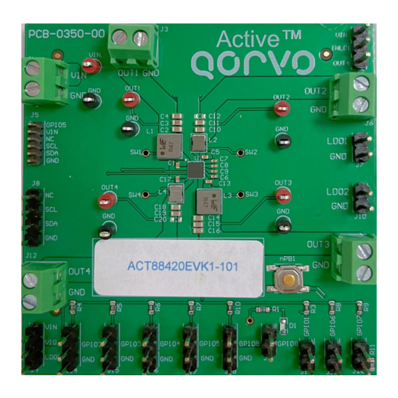
Figure 1 – EVK Picture
Innovative Power
TM
TM
ActiveSwitcher
is a trademark of Qorvo.
1
Advertisement
Table of Contents

Subscribe to Our Youtube Channel
Related Manuals for Qorvo Active ACT88420EVK1-101


Summary of Contents for Qorvo Active ACT88420EVK1-101
- Page 1 The EVK can be used as a standalone board if desired. However, to access the internal registers and to take full advantage of the IC’s capability, the user must connect the EVK kit to a PC with Qorvo’s USB-TO-I2C interface dongle and use the GUI software. The EVK provides full access to each converter’s input and output voltage, as well as all the digital control signals.
-
Page 2: Required Equipment
Power supply – 3.3V @ 5A for full power operation Oscilloscope – >100MHz, >2 channels Loads – Electronic or resistive. 3A minimum current capability. Digital Multi-meters (DMM) Windows compatible computer with spare USB port. EVK Setup Figure 2 – EVK Setup Innovative Power ActiveSwitcher is a trademark of Qorvo. -
Page 3: Hardware Setup
Rev. 1, 17-June-2022 Hardware Setup 1. Decide which voltage will power VIO_IN. Qorvo recommends powering VIO_IN from the VIN input. Connect a shorting jumper between J4-1 and J4-2 header to power VIO_IN from the VIN input voltage. 2. Connect a jumper between J2-1 and J2-2 header to power VIN_LDO1 from VIN input voltage. - Page 4 LDO1 output voltage (floating GPIO4) LDO2 LDO2 output voltage (GPIO6=H) Io_OUT1 Buck1 load current Io_OUT2 Buck2 load current Io_OUT3 Buck3 load current Io_OUT4 Buck4 load current Io_LDO1 LDO1 load current Io_LDO2 LDO2 load current Innovative Power ActiveSwitcher is a trademark of Qorvo.
- Page 5 UG148 Rev. 1, 17-June-2022 EVK Operation Turn-on Apply the 3.3V input voltage. All outputs automatically turn on with the programmed startup sequence. Test Results Innovative Power ActiveSwitcher is a trademark of Qorvo.
- Page 6 UG148 Rev. 1, 17-June-2022 Innovative Power ActiveSwitcher is a trademark of Qorvo.
- Page 7 UG148 Rev. 1, 17-June-2022 Innovative Power ActiveSwitcher is a trademark of Qorvo.
- Page 8 UG148 Rev. 1, 17-June-2022 Schematic Figure 5 – ACT88420EVK1-101 Schematic Innovative Power ActiveSwitcher is a trademark of Qorvo.
-
Page 9: Bill Of Materials
TEST POINT PC MINI .040"D BLK KeyStone 5001 TP8, TP10 5001 TP1, TP2, TP4, tpt,keystone- TEST POINT PC MINI .040"D RED KeyStone 5000 TP7, TP9 5000 IC, ACT88420-101T WLCSP36(6x6) Qorvo ACT88420-101T Innovative Power ActiveSwitcher is a trademark of Qorvo. - Page 10 UG148 Rev. 1, 17-June-2022 Layout Figure 6 – Layout Top Assembly Innovative Power ActiveSwitcher is a trademark of Qorvo.
- Page 11 UG148 Rev. 1, 17-June-2022 Figure 7 – Layout Layer 2 Innovative Power ActiveSwitcher is a trademark of Qorvo.
- Page 12 UG148 Rev. 1, 17-June-2022 Figure 8 – Layout Layer 3 Innovative Power ActiveSwitcher is a trademark of Qorvo.
- Page 13 UG148 Rev. 1, 17-June-2022 Figure 9 – Layout Bottom Layer Innovative Power ActiveSwitcher is a trademark of Qorvo.
-
Page 14: Gui Installation
Rev. 1, 17-June-2022 GUI Installation 1. Download the GUI files from Qorvo’s website and save them on your computer. 2. Plug the USB-TO-I2C dongle into a free USB port. 3. Double click on the ACT88420 GUI.exe to start the ACT88420 GUI. - Page 15 UG148 Rev. 1, 17-June-2022 Figure 11 – GUI Configuration Mode Innovative Power ActiveSwitcher is a trademark of Qorvo.
-
Page 16: Regulator Mode
The “Settings” tab is easy to read and has drop down menus that show the available choices. The “Registers” tab shows the actual register values required to achieve a desired setting. Figure 12 – GUI Setting Tab of Regulator Mode Innovative Power ActiveSwitcher is a trademark of Qorvo. - Page 17 UG148 Rev. 1, 17-June-2022 Figure 13 – GUI Register Tab of Regulator Mode Innovative Power ActiveSwitcher is a trademark of Qorvo.
-
Page 18: Button Descriptions
Active-Semi recommends reading registers each time the ACT88420 powers-up to acquire the initial register settings. Qorvo also recommends reading registers after making changes to them. Immediately reading the registers after a write confirms the changes were properly stored. This also updates the SYSTEM STATUS box to ensure that one of the changes did not generate a fault condition. - Page 19 Semi’s USB-TO-I2C dongle is connected to the USB port of the driver installed. The figure below shows the two possible indication status graphics. Dongle Dongle Connected Disconnected Figure 18 – Dongle Connection Status Innovative Power ActiveSwitcher is a trademark of Qorvo.
Need help?
Do you have a question about the Active ACT88420EVK1-101 and is the answer not in the manual?
Questions and answers