Table of Contents
Advertisement
Quick Links
UG132
1.0, 05-Dec-2019
ACT86600EVK1-101 User's Guide
Description
This document describes the characteristics and operation of the Qorvo ACT86600EVK1-101 evaluation kit
(EVK). It provides setup and operation instructions, schematic, layout, BOM, and test data. This EVK
demonstrates the ACT86600QM101 ActivePMU power management IC. Other ACT86600QMxxx options can
be evaluated on this EVK by replacing the IC and any other necessary components.
Features
The EVK can be used as a standalone board if desired. However, to access the internal registers and to take
full advantage of the IC's capability, the user must connect the EVK kit to a PC with Qorvo's USB-TO-I2C
interface dongle and use the GUI software. The EVK provides full access to the each converter's input and
output voltage, as well as all the digital control signals. This gives the user the flexibility to configure the EVK
to match their real-world system.
Note that the ACT86600EVK1-101 is specifically configured for the ACT86600QM101.
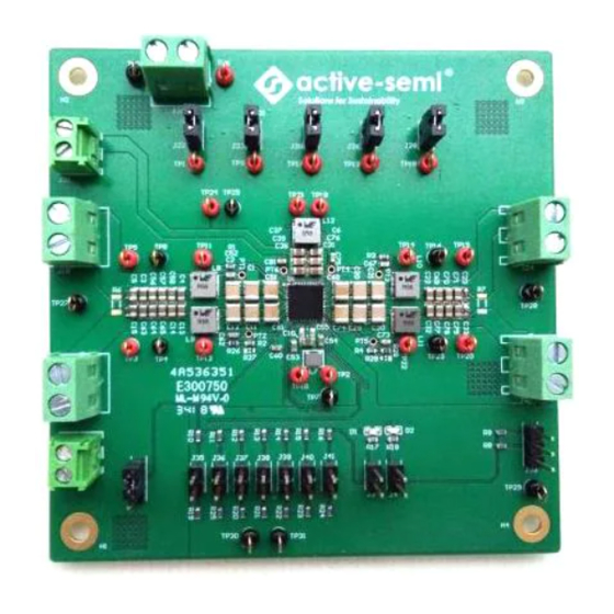
Figure 1 – EVK Picture
TM
Innovative Power
TM
ActiveSwitcher
is a trademark of Qorvo.
1
Advertisement
Table of Contents

Subscribe to Our Youtube Channel
Related Manuals for Qorvo ActiveSwitcher ACT86600EVK1-101


Summary of Contents for Qorvo ActiveSwitcher ACT86600EVK1-101
- Page 1 The EVK can be used as a standalone board if desired. However, to access the internal registers and to take full advantage of the IC’s capability, the user must connect the EVK kit to a PC with Qorvo’s USB-TO-I2C interface dongle and use the GUI software. The EVK provides full access to the each converter’s input and output voltage, as well as all the digital control signals.
-
Page 2: Evk Contents
Power supply – 12V @ 7.5A or 5V @ 18A for full power operation Oscilloscope – >100MHz, 4 channels Loads – Electronic or resistive. 8.0A minimum current capability. Digital Multimeters (DMM) Windows compatible computer with spare USB port. Hardware Setup Figure 2 – EVK Setup Innovative Power ActiveSwitcher is a trademark of Qorvo. -
Page 3: Quick Start
Quick Start Hardware Setup 1. Decide which voltage will power VIO. Qorvo recommends powering VIO from the VCC5 output for general evaluation. Install a shorting jumper between J1-1 and J1-2 to power VIO from VCC5. Or use a wire to connect J1-2 to any Buck converter output. - Page 4 Refer to Figure 4 to ensure the correct polarity of the connection. As a guide, use the “Qorvo” logo (or “Active-Semi” logo) on the top of the dongle so the black wire is connected to the Dongle GND pin.
-
Page 5: Sleep Mode
Enter Sleep Mode by changing voltage level of GPIO4 from low to high. In Sleep Mode, the BUCK1/2/3 are still on, meanwhile BUCK4 and BUCK-BOOST outputs turn off. This is the default EVK sleep setting. However the sleep/deep sleep settings are configurable. Innovative Power ActiveSwitcher is a trademark of Qorvo. - Page 6 UG132 1.0, 05-Dec-2019 Schematic Figure 5 – ACT86600EVK1-101 Schematic Innovative Power ActiveSwitcher is a trademark of Qorvo.
- Page 7 UG132 1.0, 05-Dec-2019 Layout Figure 6 – Layout Top Assembly Innovative Power ActiveSwitcher is a trademark of Qorvo.
- Page 8 UG132 1.0, 05-Dec-2019 Figure 7 – Layout Top Layer Innovative Power ActiveSwitcher is a trademark of Qorvo.
- Page 9 UG132 1.0, 05-Dec-2019 Figure 8 – Layout Layer 2 (internal GND plane) Innovative Power ActiveSwitcher is a trademark of Qorvo.
- Page 10 UG132 1.0, 05-Dec-2019 Figure 9 – Layout Layer 3 Innovative Power ActiveSwitcher is a trademark of Qorvo.
- Page 11 UG132 1.0, 05-Dec-2019 Figure 10 – Layout Bottom Layer Innovative Power ActiveSwitcher is a trademark of Qorvo.
-
Page 12: Bill Of Materials
5000 TP17, TP18, TP19, TP20, TP21, TP22, TP24 TP4, TP7, TP8, TP16, tpt, Key- TP23, TP25, TP26, TP27, Test point, 0.050 hole, black stone- Keystone keystone-5001 TP28, TP29, TP30, TP31 5001 Innovative Power ActiveSwitcher is a trademark of Qorvo. - Page 13 UG132 1.0, 05-Dec-2019 Jumpers at J22/J23/J3 0/J26/J28; Shunt, 2.54 mm Standard Standard at J1 (be- tween pin1 and pin2) Shanghai PCB, 4-Layer FR4, Fast-pcb PCB-0326-02 90*90*1mm Tech.Co, Innovative Power ActiveSwitcher is a trademark of Qorvo.
-
Page 14: Gui Installation
1. Contact Qorvo for the GUI files and save them on your computer. 2. Plug the USB-TO-I2C dongle into a free USB port. 3. Follow the instructions in the “Qorvo's GUI and Dongle Driver Installation Rev1.1.pdf” file. Figure 11 – Dongle Driver 4. - Page 15 UG132 1.0, 05-Dec-2019 Figure 12 – GUI Basic Mode Innovative Power ActiveSwitcher is a trademark of Qorvo.
-
Page 16: Advanced Mode
Button Descriptions OPEN: Open function allows the user to open an ACT86600’s register information data from a saved file (.iact or.xml files). The file should be either provided by Qorvo or saved by the same software previously. Innovative Power ActiveSwitcher... - Page 17 1.0, 05-Dec-2019 Figure 14 – Open Button Save: Save function allows the user to save the ACT86600 register information to an .iact or .xml file. Qorvo recommends user to save the register information to an .iact file. Figure 15 – Save Button Read: Clicking on this button reads the ACT86600 registers and displays the values in the GUI.
- Page 18 The register information cannot be updated without the correct passcode. Figure 19 – Passcode Disable Dongle Connection Status: The GUI also contains a dongle is connected status which indicates that Qorvo’s USB-TO-I2C dongle is connected to the USB port of the driver installed. The figures below show the possible indication status graphics.
- Page 19 Figure 21 – Dongle is connected to PC/GUI software, and not connected to EVK (or connected to EVK but EVK is not working) Figure 22 – Dongle is connected to PC/GUI software, and connected to EVK (and EVK is working) Innovative Power ActiveSwitcher is a trademark of Qorvo.
Need help?
Do you have a question about the ActiveSwitcher ACT86600EVK1-101 and is the answer not in the manual?
Questions and answers